immediately powers the server off on a button press, since there is no concept of soft shutdown
in this state.
In the event that the OS is absent or hung, or that the manageability subsystem (specifically the
BMC) in the server is not responding, a greater than four second press of the power button is
required to power down the system (a less than four second press on the power button has no
effect).
To ensure that the system powers up in a deterministic fashion, the power button must be masked
for four seconds after a power-down.
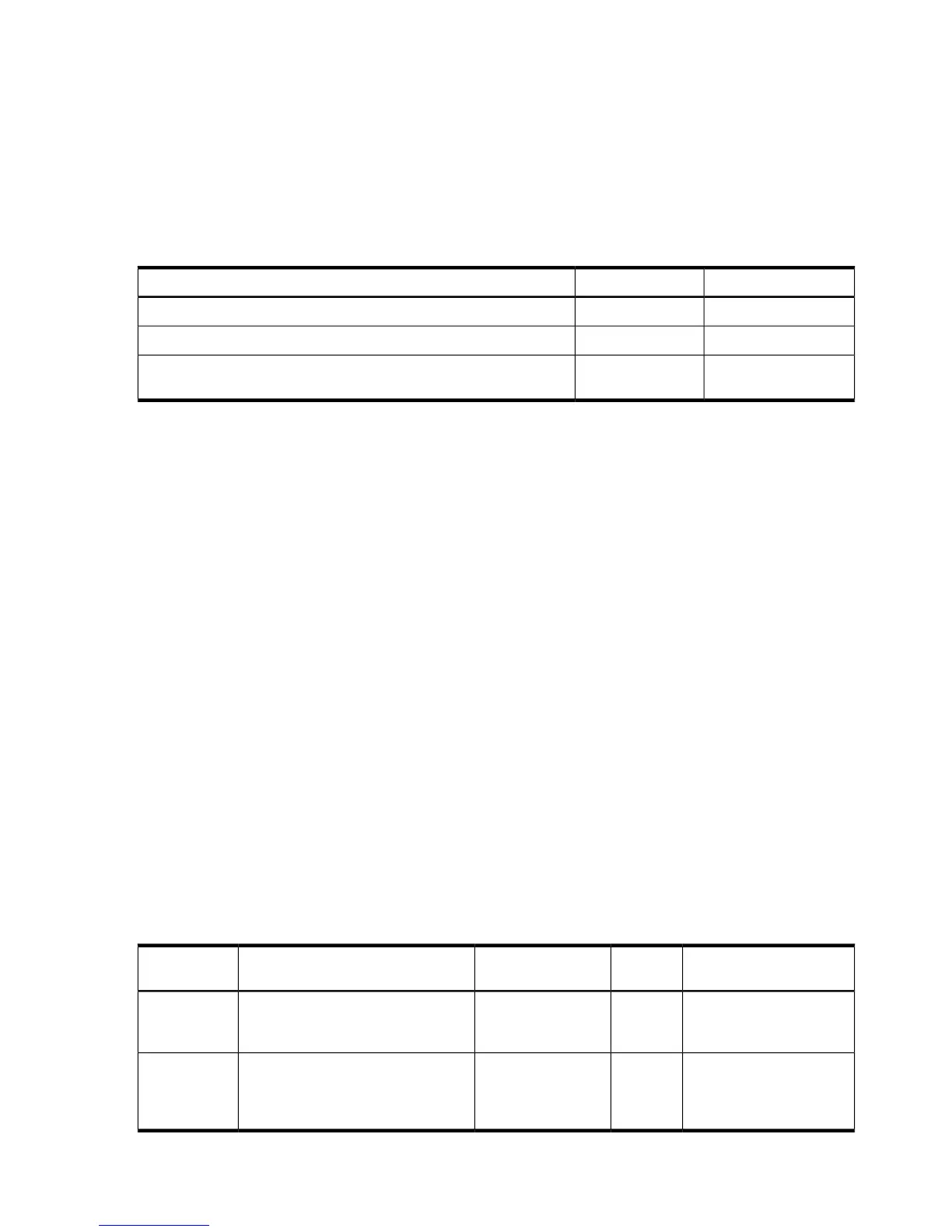
Table 5-19 Power LED States
LED ColorFlash RateDefinition
LED OffNo ac power to the system
GreenSteadySystem power is turned on
AmberSteadySystem is shut down, but ac and housekeeping (standby) power are
active.
For high availability and safety reasons, this LED runs off the power rails, rather than under
firmware control.
Cooling Subsystem
The three fan cooling zones located within the rx2660 server provide N+1 redundancy for the
server using three identical dual fan assembly CRUs. In turn, each dual fan assembly CRU
provides additional N+1 redundancy for the fan cooling zone it controls. Each dual fan assembly
CRU is identified by the server as fans 1 through 12 both for logging purposes and for fault
identification on the diagnostic LED panel.
External cooling fan CRU failures are identified visually by a single green LED on the dual fan
assembly CRU that is turned on when one or both of the fans fail; logged as an IPMI event by
fan sensor logic; and identified as a fan assembly CRU failure by the BMC turning on the
appropriate LEDs on the System Insight Display panel.
Cooling Subsystem Behavior
The BMC chip located on the system board CRU controls fan speed on ambient air temperatures,
chip temperatures, server configuration, and fan operation or failure. Air is drawn through the
front of the server and pushed out the rear by the cooling fans. There are three cooling zones
cooled by the 12 server fans. Zone 1 is cooled by fans 1 through 4, zone 2 is cooled by fans 5
through 8, and zone 3 is cooled by fans 9 through 12. Each zone can have one fan failure and still
sufficiently cool the server. You can display fan status remotely with the iLO 2 MP ps command.
Within the HP integrity rx2660 server, temperature sensors report server temperatures to the
BMC, which controls fan speed based on this information.
Table 5-20 Cooling Subsystem Events That Light System Insight Display LEDs
NotesSourceCauseSample IPMI EventsDiagnostic
LED(s)
Cleared when fan is
replaced
BMCFan has either
previously failed or
is degrading
Type 02h, 0Ah:07h:01h
COOLING_UNIT_WARNING
Fans (1-12)
Cleared when fan is
replaced
BMCFan has failed and
no longer meets
Type 02h, 0Ah:07h:02h
COOLING_UNIT_FAILURE
Fans (1-12)
minimum
requirements
130 Troubleshooting