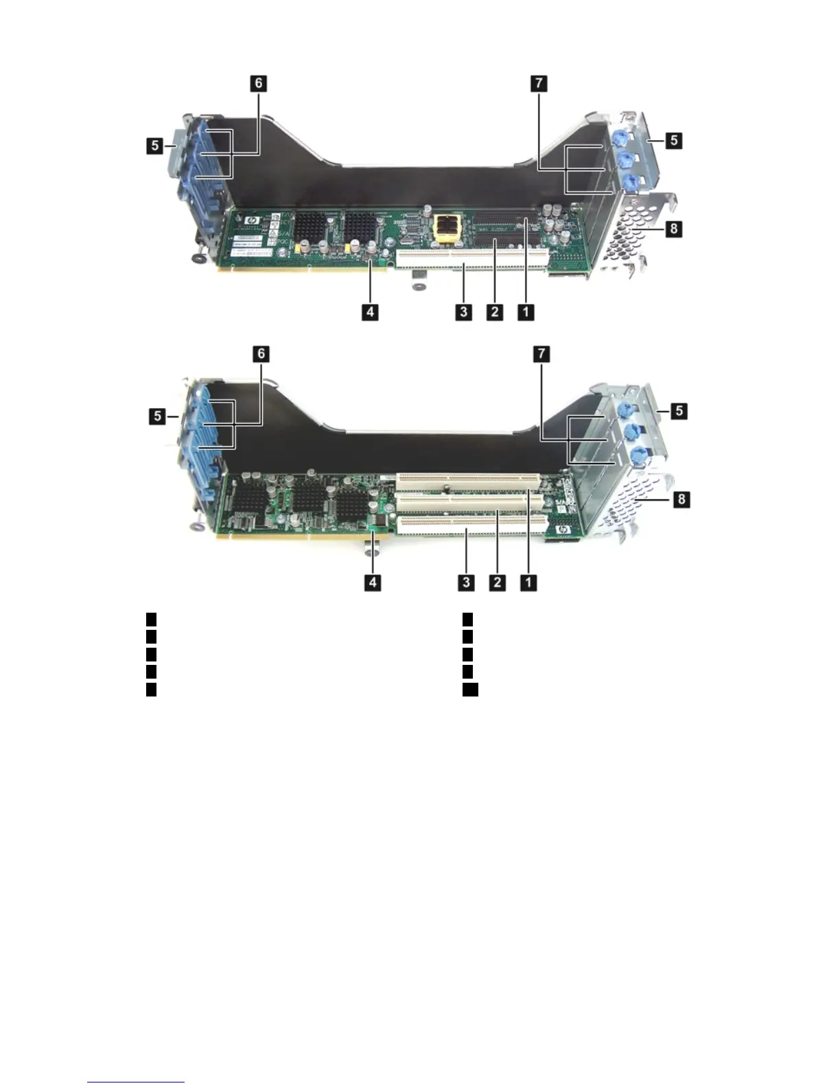
Figure B-2 Removing the I/O Backplane Assembly
6
Gate latches (for full-length cards)
1
Slot 1 (266 MHz)
2
Slot 2 (133 MHz)
7
Bulkhead fillers
8
Sheet metal enclosure
3
Slot 3 (266 MHz)
4
I/O backplane
9
I/O backplane T-15 screws
105
Bulkhead T-15 thumbscrewsI/O backplane assembly guide tabs
Removing the PCI-X I/O Backplane Board from the I/O Backplane Assembly
Use this procedure to remove the I/O backplane from the I/O backplane assembly.
1. Remove the three T-15 screws that attach the PCI-X backplane to the I/O backplane assembly.
Figure B-2 (page 207) shows the locations of the T-15 screws.
2. Slide the PCI-X backplane down to release it from the posts on the I/O backplane assembly,
and lift it from the I/O backplane assembly. Figure B-3 (page 208) shows the locations of the
posts on the I/O backplane assembly.
Upgrading the I/O Backplane 207