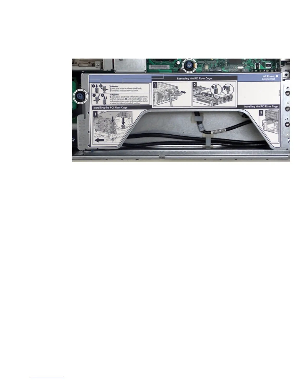
5. Loosen the two captive screws. See Figure 6-24 for the screw locations.
a. Press the blue button to release the black knob.
b. Turn the black knob counter-clockwise until the captive screw is free from the system
board.
Figure 6-24 Removing the I/O Backplane Assembly
6. Lift the assembly straight up and out of the server. Figure 6-25 (page 168) shows the PCI-X
and the PCIe/PCI-X backplane assemblies.
Removing and Replacing the I/O Backplane Assembly 167