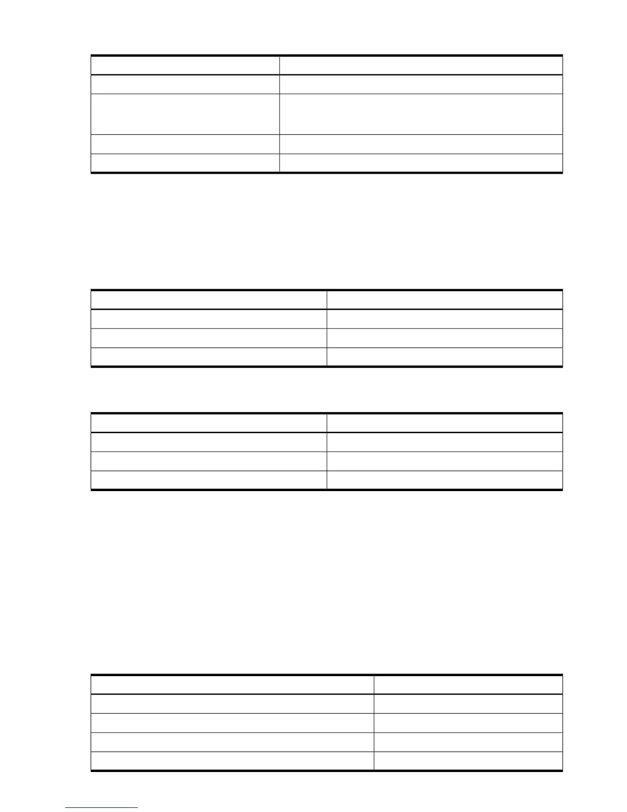
Table 1-7 iLO 2 MP Status LEDs
LED StateiLO 2 MP Status LED
Flashing greeniLO 2 MP heartbeat
Off: The LED is solid amber when ac power is applied. It remains
solid amber for a few seconds until the iLO 2 MP completes its
self-test; then the LED turns off.
iLO 2 MP self-test
Flashing greenBMC heartbeat
Solid greenStandby power
System LAN
The system LAN functionality is integrated into the system board. The following describes the
system LAN ports:
• Two RJ-45 style 10 Base-T/100 Base-T/1000 Base-T system LAN ports.
Table 1-8 lists the core LAN link status LEDs and states.
Table 1-8 System LAN Link Status LEDs
LED StateLink Status
Blinking greenActivity
Solid greenLink with no activity
OffNo link
Table 1-9 lists the system LAN link speed LEDs and states.
Table 1-9 System LAN Link Speed LEDs
LED StateLink Status
Solid orange1000 Mb
Solid green100 Mb
Off10 Mb
Power Supply
The server is equipped with one or two power supplies, labeled PS1 and PS2. Each power supply
has an ac input receptacle and an LED that shows the power state of the server. See Figure 1-10
(page 32) for the LED location.
The server has three power states: standby power, full power, and off. To achieve the standby
power state, plug the power cord into the appropriate receptacle at the rear of the server. To
achieve full power, plus the power cord into the appropriate receptacle, and either push the
power button or enter the iLO 2 MP PC command. In the off state, power cords are not connected
to a power source. For more information on power states, see “Power States” (page 78).
Table 1-10 lists the power supply LED states.
Table 1-10 Power Supply LED
Power Supply LEDPower Supply Condition
OffNo ac power
Blinking greenac power; standby power on
Solid greenFull power on; normal operation
Blinking amberPower supply failure
34 Overview