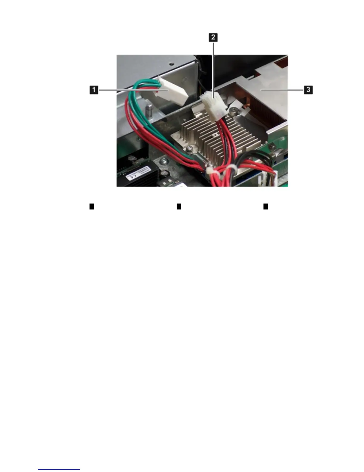
Figure 3-13 Processor Power Connectors
321
ProcessorSystem board power
cable and connector
Processor power
cable and connector
13. Close the processor cage.
a. Grasp the processor cage handle and rotate the cage closure inward toward the rear of
the assembly until it is completely closed.
b. Apply adequate force to push the handle down until it is flush with the cage.
14. Replace the airflow guide if you are finished installing additional components. See “Replacing
the Airflow Guide” (page 57).
15. Replace the top cover if you are finished installing additional components. See “Replacing
the Top Cover” (page 63)
Replacing the Airflow Guide
Use this procedure to replace the airflow guide in the server when you are finished installing
additional equipment into the server.
To replace the airflow guide, follow these steps:
1. Ensure the fan carrier handle is raised approximately 5 cm (2 in) to allow clearance for the
airflow guide replacement. Figure 3-14 (page 58) shows the fan carrier handle raised.
2. Place the airflow guide on the edge of the fan carrier and set it down into place on the
processor cage (1).
3. Push the fan carrier handle down until it is flush against the airflow guide (2).
Installing Additional Components 57