3. Lift the assembly straight up and out of the server.
NOTE: Depending on your configuration, you have one of the I/O backplane assemblies
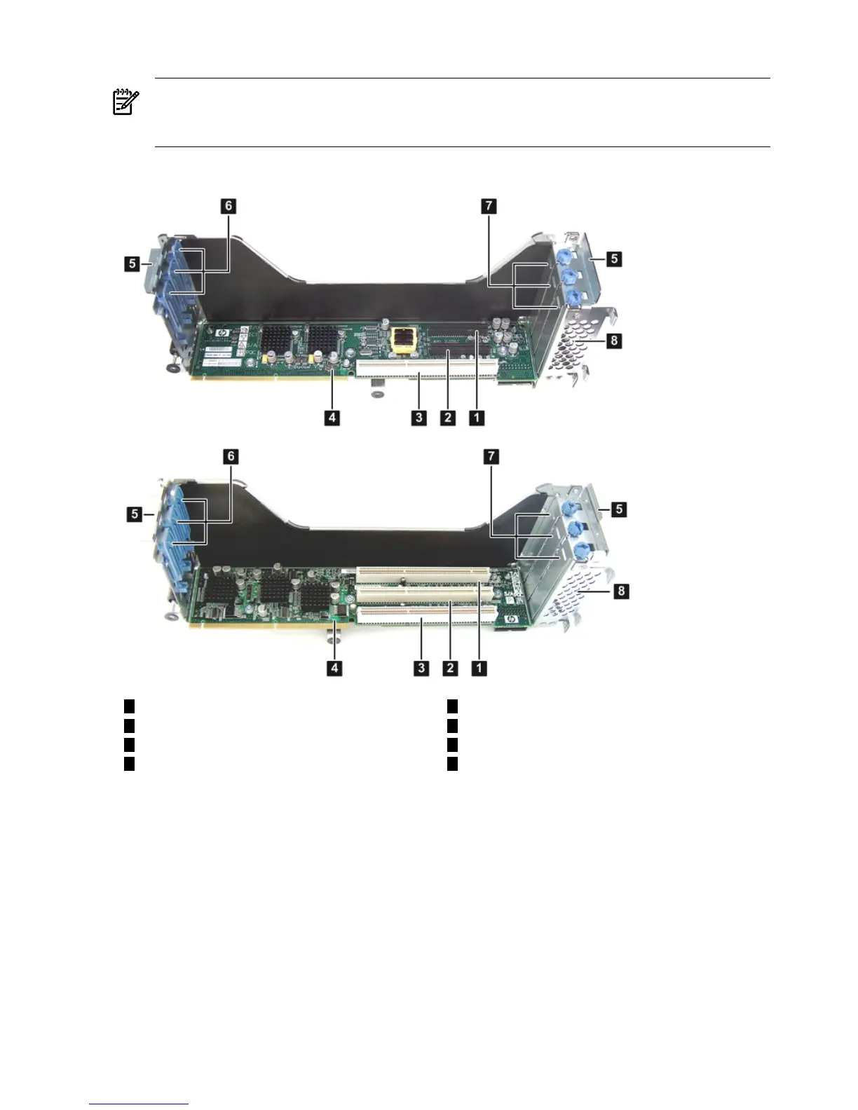
shown in Figure 3-16 (page 60). The top I/O backplane assembly is a PCIe/PCI-X backplane
assembly, and the bottom is a PCI-X backplane assembly.
Figure 3-16 I/O Backplane Assemblies
5
Guide tabs
1
Slot 1 (top, PCIe; bottom PCI-X)
2
Slot 2 (top, PCIe; bottom PCI-X)
6
Gate latches (for full-length cards)
7
Bulkhead fillers
3
Slot 3 (PCI-X)
4 8
I/O backplane riser board (top, PCIe; bottom
PCI-X)
Sheet metal enclosure
Installing a PCIe/PCI-X Card
To install a PCIe/PCI-X card, follow these steps:
1. Select an empty slot that is appropriate for the card you are installing. X shows both a PCI-X
and PCIe/PCI-X riser boards.
2. Remove the PCIe/PCI-X bulkhead filler by unscrewing the blue captive screw using a
Torx-T15 screwdriver.
60 Installing the Server