3. If the activity LED stays illuminated steady green on any SAS disk drives (after the drive spins
up), the drive might not be seated correctly. Check installation as follows:
a. Turn off the server power button and unplug the AC power cords and any cables.
b. Re-seat all of the SAS disk drives installed in the server.
c. Reconnect the AC power cords and any cables. Restart the server to determine whether
the LEDs now become illuminated during the boot. If not, contact your reseller.
4. Use the UEFI Shell map -r command to check the SAS drives.
System LAN LEDs
Four system LANs are located on the rear bulkhead of the server. These LANs are connected to
the system board.
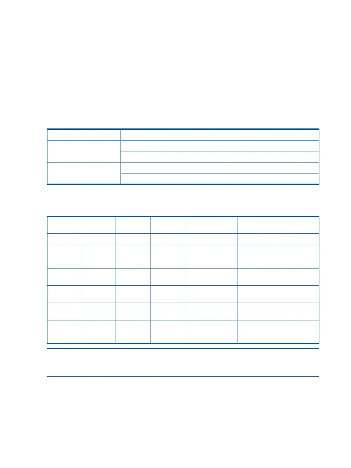
Table 38 Gb LAN connector LEDs
DescriptionLED
Green: linkLink (left)
Off: no link
Green: linkActivity (right)
Off: No link
Troubleshooting the boot process
Table 39 Normal boot process LED states
Normal power-up through OS bootSIDPowerHealthSystem Event
Log
Step
No AC power to the system.OffOffOffOff1
System is shut down, but AC
power and standby power is
active.
OffSteady amberOffOff2
System power rails are on when
power switch is toggled.
OffSteady greenOffOff3
System power rails are on; iLO MP
drives system health LED.
OffSteady greenSteady greenOff4
System is booting firmware (has
passed BOOT_START in firmware).
OffSteady greenSteady greenOff5
System has finished booting
firmware and an OS is either
booting or running.
OffSteady greenSteady greenSteady green6
NOTE: In the standard boot process, shown in the preceding table, even though the iLO MP is
running while the system is shut down (power LED is steady amber), it does not drive the system
health LED to steady green until +12 V DC power from the Bulk Power Supplies is applied.
The following list itemizes the steps that characterize basic platform boot flow. Step numbers
provided correspond to the steps in Table 39 (page 88).
3. System power switch turns on bulk power supplies and fans, and releases RESET on all processors
simultaneously, when toggled on.
5. Initial processor firmware code fetch is PAL code from EEPROM connected directly to the CPU,
retrieved 4 bytes at a time by DMDC in ICH10 (No shared memory or I/O devices are available
at this time; for example they are not initially configured).
HP Confidential88 Troubleshooting

 Loading...


