320
IPv6 PIM-SM admin-scoped zone configuration example
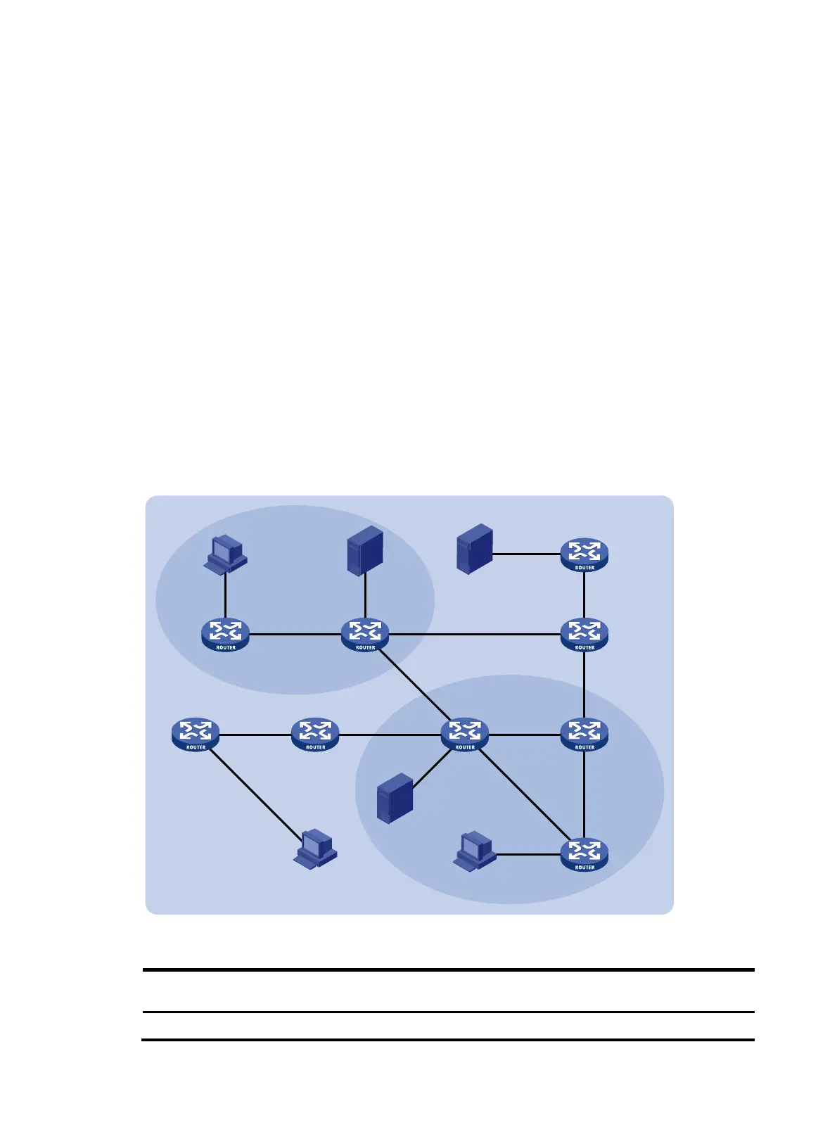
Network requirements
As shown in Figure 99:
• VOD streams are sent to receiver hosts in multicast. The entire IPv6 PIM-SM domain is divided into
IPv6 admin-scoped zone 1, IPv6 admin-scoped zone 2, and the IPv6 global-scoped zone. Router B,
Router C, and Router D are ZBRs of the three zones, respectively.
• Source 1 and Source 2 send different IPv6 multicast data to the IPv6 multicast group FF14::101. Host
A receives the IPv6 multicast data only from Source 1, and Host B receives the IPv6 multicast data
only from Source 2. Source 3 sends IPv6 multicast data to the IPv6 multicast group FF1E::202. Host
C is an IPv6 multicast receiver for the IPv6 multicast group FF1E::202.
• GigabitEthernet 2/1/2 of Router B acts as a C-BSR and a C-RP for IPv6 admin-scoped zone 1, and
GigabitEthernet 2/1/1 of Router D acts as a C-BSR and a C-RP for IPv6 admin-scoped zone 2. Both
of the two interfaces are designated to the IPv6 multicast groups with the scope field of 4.
GigabitEthernet 2/1/1 of Router F acts as a C-BSR and a C-RP for the IPv6 global-scoped zone,
and is designated to the IPv6 multicast groups with the scope field value of 14.
• MLDv1 separately runs between Router A, Router E, Router I, and the receivers that directly connect
to them.
Figure 99 Network diagram
Table 23 Interface and IPv6 address assignment
Device Interface
IPv6
address
Device Interface IPv6 address
Router A GigabitEthernet 2/1/1 1001::1/64
Router E GigabitEthernet 2/1/2 3002::2/64
Router A
Router B
ZBR
Router C
ZBR
Router D
ZBR
Router E
Router HRouter I
Router F
Router G
Source 3
Source 1
Source 2
Receiver
Host A
GE2/1/3
G
E2/1
/2
GE2/1/
4
GE2/1/1
GE2/1/5 GE2/1/1
GE2/1/2
GE2/1/3
GE2/1/2
GE2/1/1
GE2/1/2
GE2/1/1
G
E2
/1/2
GE2/1/3
GE2/1/1
GE2/1/1
GE2/1/2 GE2/1/2
GE2/1/
1
GE2/1/1 GE2/1/1
GE2/1/3
GE2/1/4 GE2/1/3GE2/1/2
GE2/1/2
Receiver
Host B
Receiver
Host C
IPv6 PIM-SM
IPv6 global-scope
IPv6 admin-scope 1
IPv6 admin-scope 2