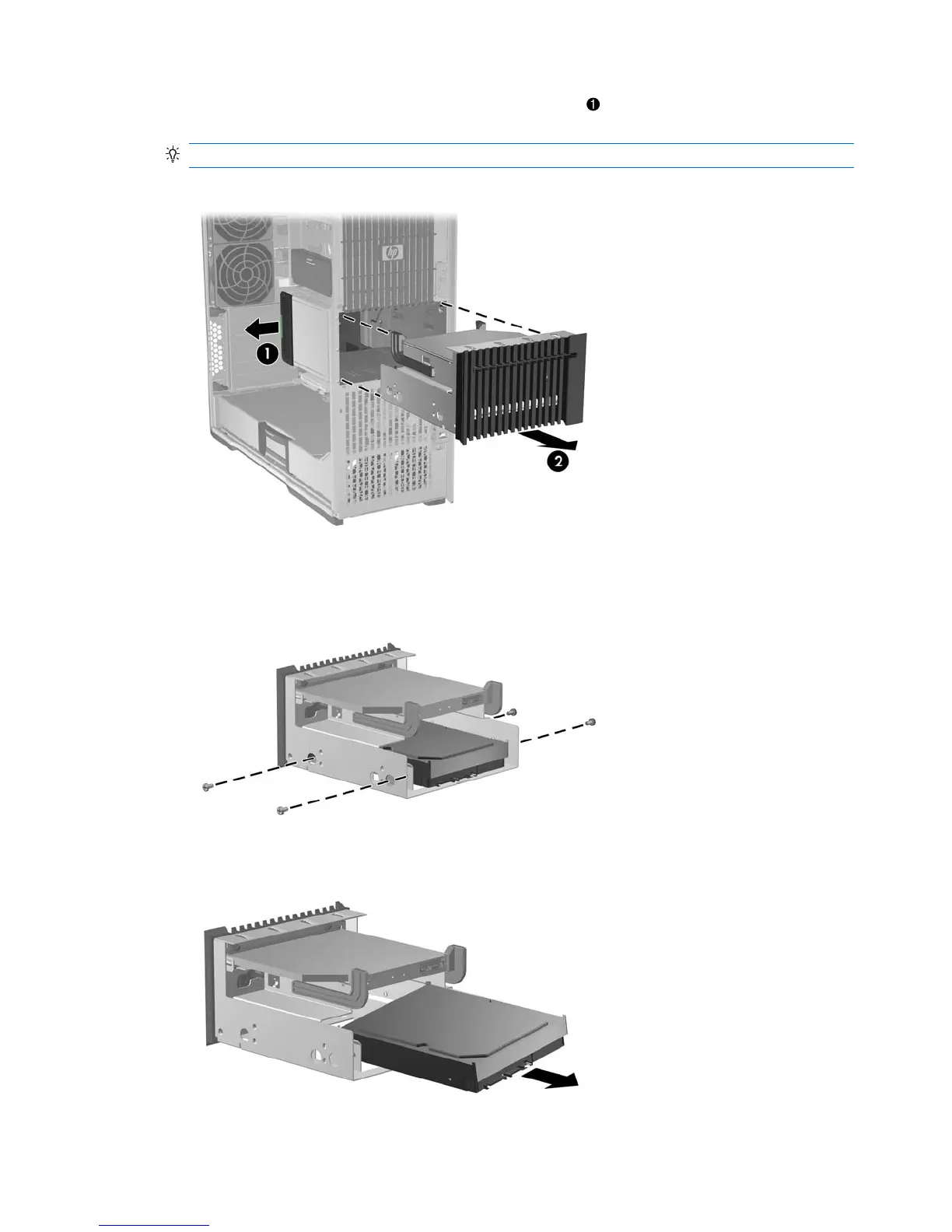
7. Lift and hold the drive release latch at the green touch point , and then slide the slot load assembly
out of the chassis
2
as shown in the following figure.
TIP: Push on the slot load assembly from the inside of the chassis.
Figure 5-43 Removing the slot load assembly
8. Remove the four Torx slotted screws that secure the drive in the slot load bay as shown in the
following figure.
Figure 5-44 Removing the drive screws
9. Remove the drive from the slot load bay as shown in the following figure.
Figure 5-45 Removing the drive from the slot load carrier
108 Chapter 5 Replacing components ENWW