Component locations
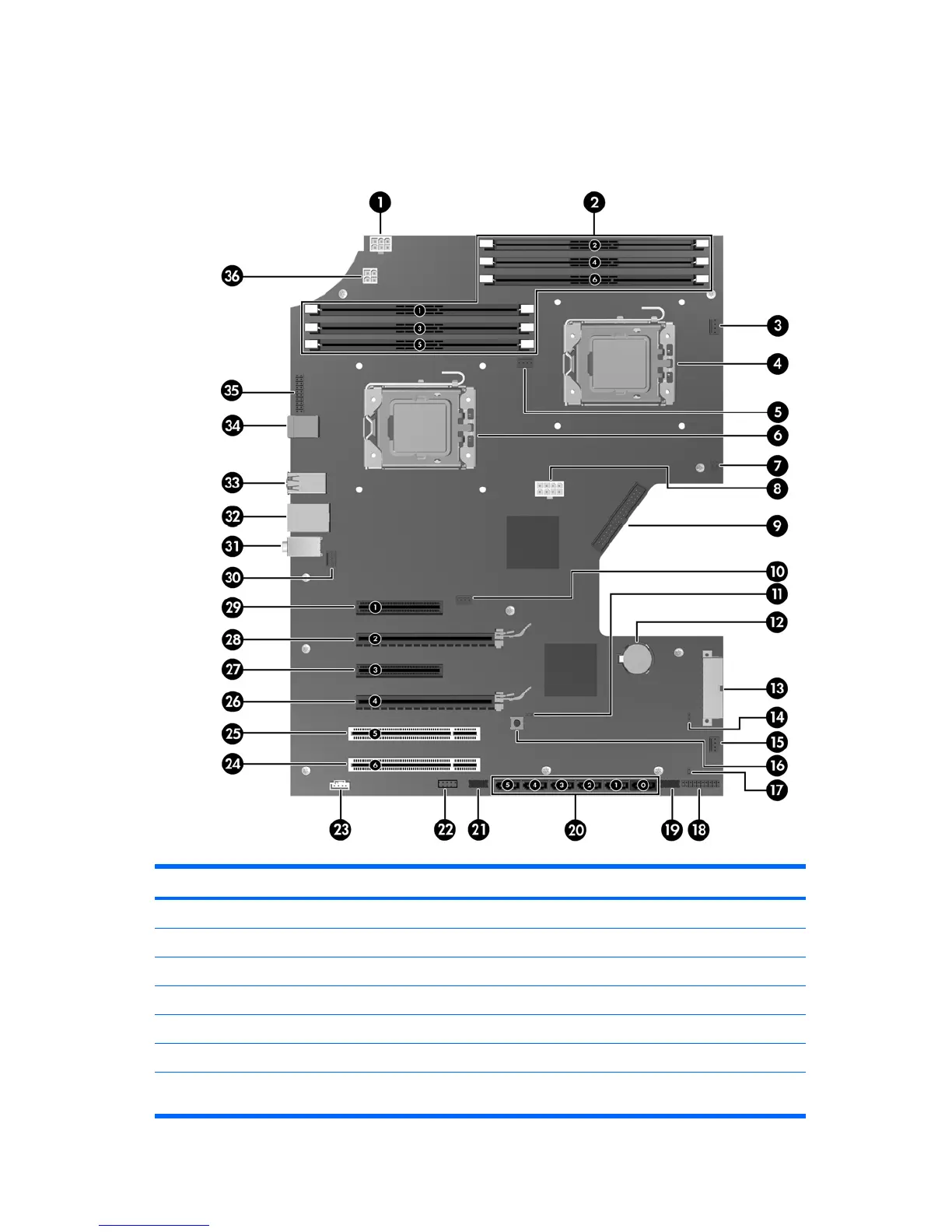
The following illustration and table identify workstation system board components.
Figure 5-1 System board component locations
Table 5-2 System board components ID
Item Component Item Component Item Component
1 Memory power 13 Main power 25 PCI 32/33
2 Memory sockets 14 Crisis recovery jumper 26 PCIe2 - x16
1
3 CPU1 fan 15 Front system fan 27 PCIe - x8(4)
2
4 CPU1 socket 16 Clear CMOS button 28 PCIe2 - x16
1
5 CPU0 fan 17 HDD LED 29 PCIe2 - x8(4)
2
6 CPU0 socket 18 Power button/LED/speaker 30 Rear system fans
7 Side access panel solenoid
lock
19 Front USB 31 Audio
70 Chapter 5 Replacing components ENWW