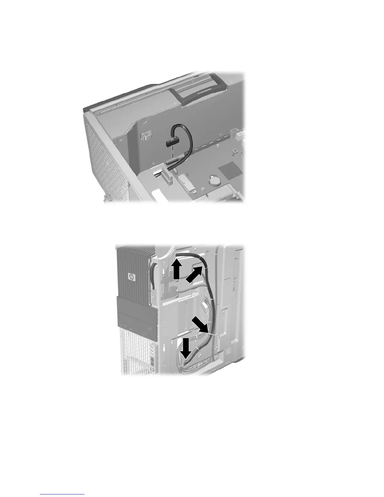
6. Disconnect the power switch cable assembly cable from the system board as shown in the following
figure.
Figure 5-18 Disconnecting the power switch cable assembly cable
7. Carefully guide the cable out of the chassis from its location behind the right side panel as shown
in the following figure.
Figure 5-19 Removing the power switch cable
Installing the power switch cable assembly
To replace the power switch cable assembly, reverse the removal steps.
Optical bay filler tray
If an optical bay slot is left empty, a filler tray must be placed in the slot to ensure proper electromagnetic
interference (EMI) protection and cooling air efficiency.
ENWW Removing and installing components 89