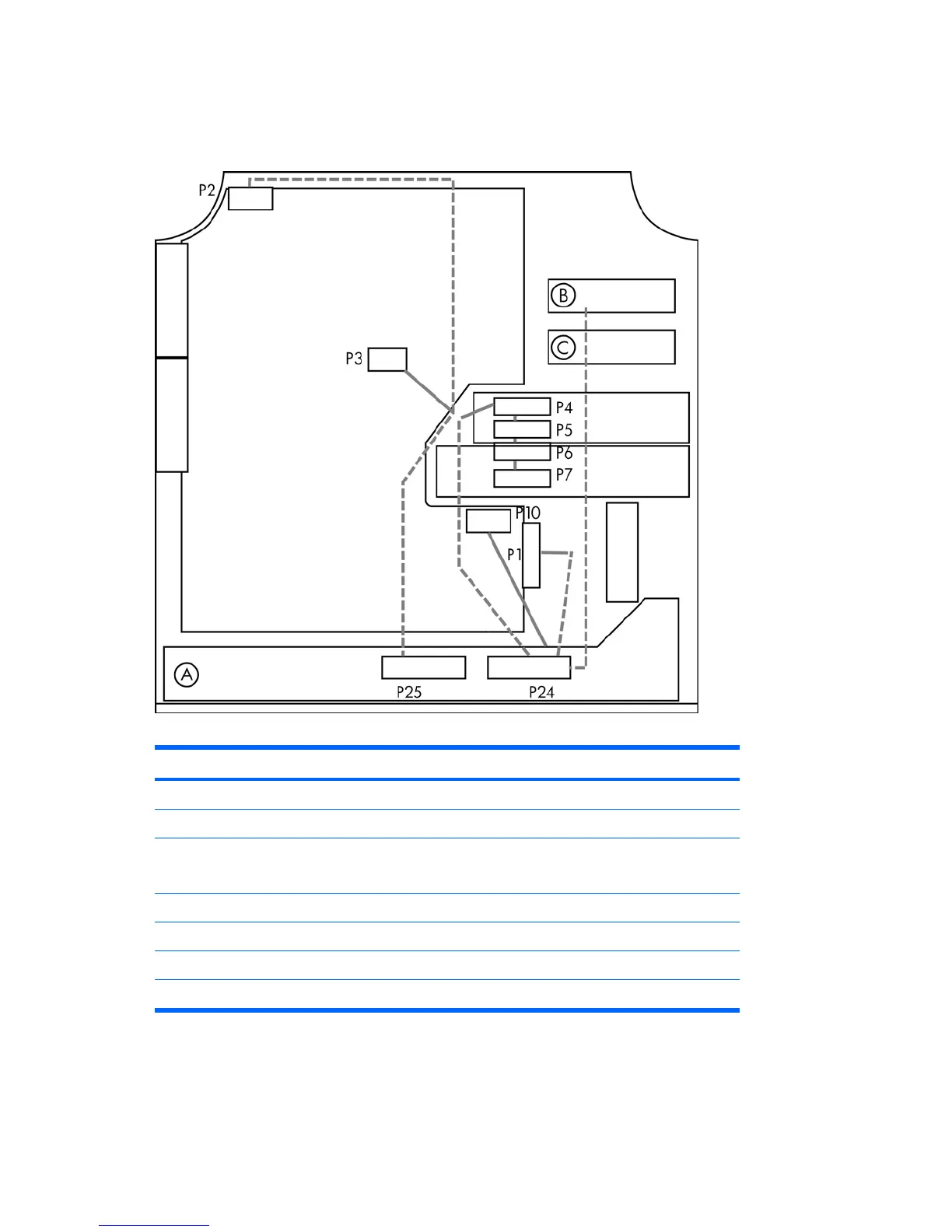
For help with identifying power cables, see the following figure and table. Ensure that all cables are
routed or tied so they cannot interfere with the processor heatsink fans.
Figure 5-10 Power connector identification for a typical configuration
Table 5-4 Power connector description
Item Description Item Description
P1 Main power P10 Graphics power
P2 Memory power P24 Power to main and drives
P3 CPU power
Memory power
P25 Power to CPU and memory
P4 SATA power A Power supply
P5 SATA power B HDD bay 0
P6 IDE power C HDD bay 1
P7 FDD power
82 Chapter 5 Replacing components ENWW