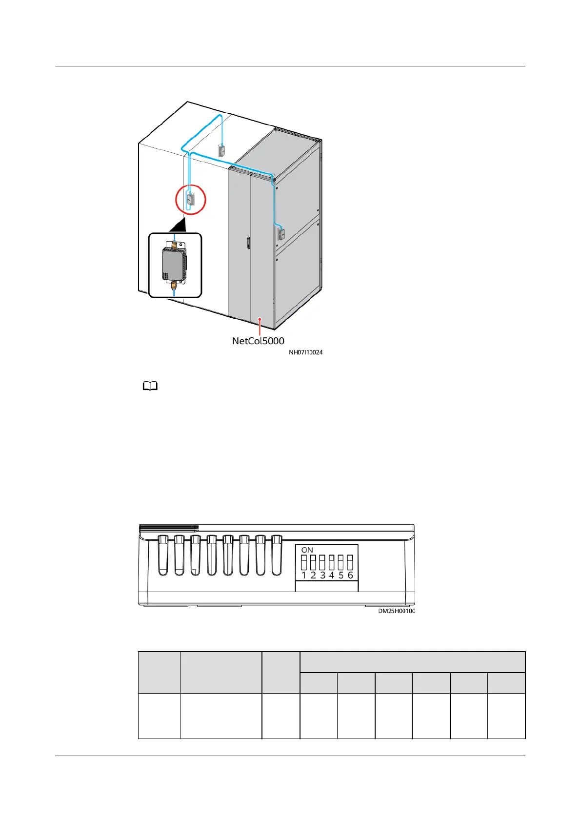
Figure 4-86 Cables routed outside the cabinet
● The T/H sensors should be 1.5 m above the ground (33 U).
● Each smart cooling product supports a maximum of ten T/H sensors.
● The RS485 ports at both ends of a T/H sensor (33010516) do not distinguish between
the input and output, and they can be connected directly in series.
Step 2 Set the DIP switches of T/H sensors. Table 4-18 shows how to set the DIP switches
for T/H sensors.
Figure 4-87 Position of the DIP switch on a T/H sensor
Table 4-18 DIP switch setting on a T/H sensor
Locati
on
Display Name Addr
ess
DIP Switch Sequence No.
1 2 3 4 5 6
Air
return
side
Return air 2
temp/humid
1 ON OFF OFF OFF OFF OFF
NetCol5000-A050 In-row Air Cooled Smart Cooling
Product
User Manual 4 Installation
Issue 08 (2021-09-17) Copyright © Huawei Technologies Co., Ltd. 109
 Loading...