v 1.0 — February 2020 Altanium Matrix5
212 Remove and Replace the MCU
6. Find the two top fasteners that hold the MCU to the mounting bracket and loosen them
with a 4 mm right angle Allen key or hex wrench. Refer to Figure 15-18.
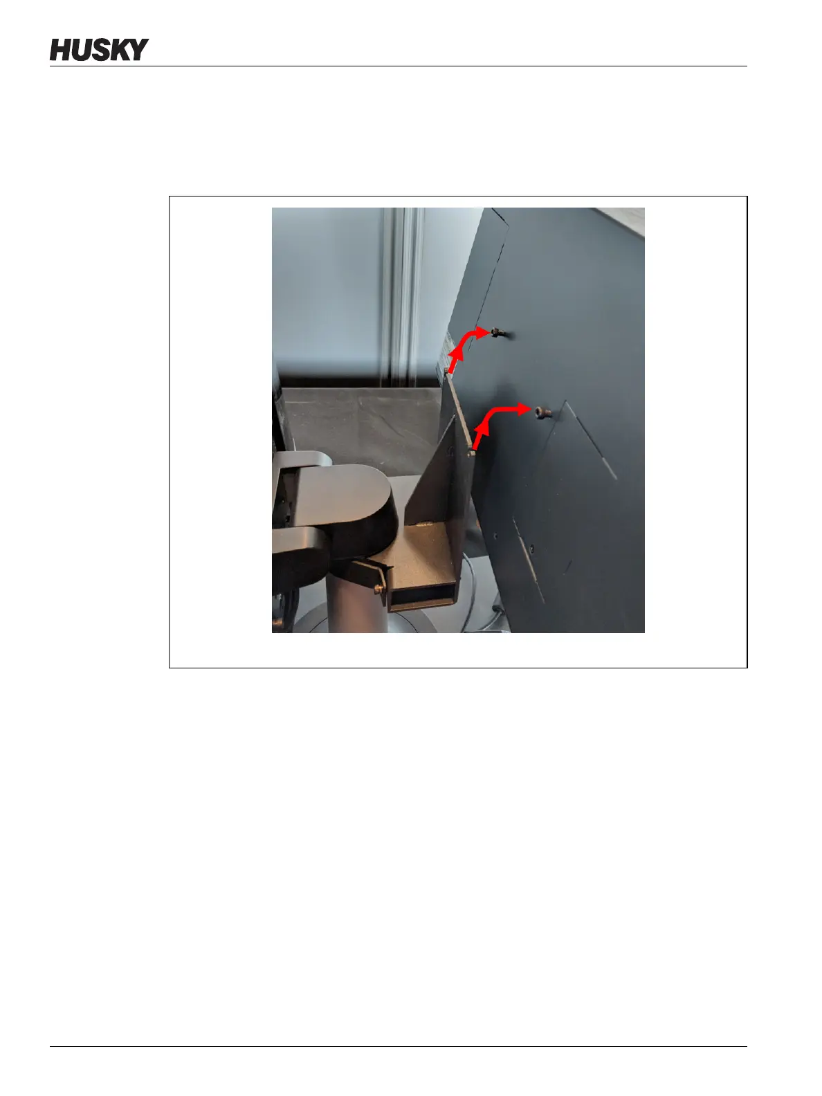
7. Securely hold the MCU and slide it up until the screws have cleared the upper mounting
slots and pull forward to remove the MCU from the mounting bracket. Refer to
Figure 15-19.
8. When you install the replacement MCU, make sure that the screws are pre-installed on
the upper threaded studs and the screws are left off the lower studs on the back of the
touch monitor.
9. Securely hold the MCU and slide it down onto the mounting bracket, so the top MCU
screws go into the bracket slots.
10. Install the two bottom socket cap screws.
11. Use a 4 mm right angle Allen key or hex wrench to tighten all four screws.
12. Connect the Touch Screen Signal, Touch Monitor Power, and VGA or LCD1 (HDMI)
connectors at the bottom of the MCU enclosure.
13. Connect all other cables to the bottom of the MCU enclosure if your system has other
options.
14. Remove the lock out equipment and tag from the main power switch.
15. Energize the system at the main power switch.
Figure 15-19 Remove the MCU from the Bracket