v 1.0 — February 2020 Altanium Matrix5
220 Install the Alternative Mounted Operator Interface
To install the alternative mounted operator interface, do the steps that follow:
1. If necessary, de-energize the system at the Altanium main power switch. Refer to
Figure 15-2.
2. If necessary, lock out and tag the main power switch in accordance with local codes.
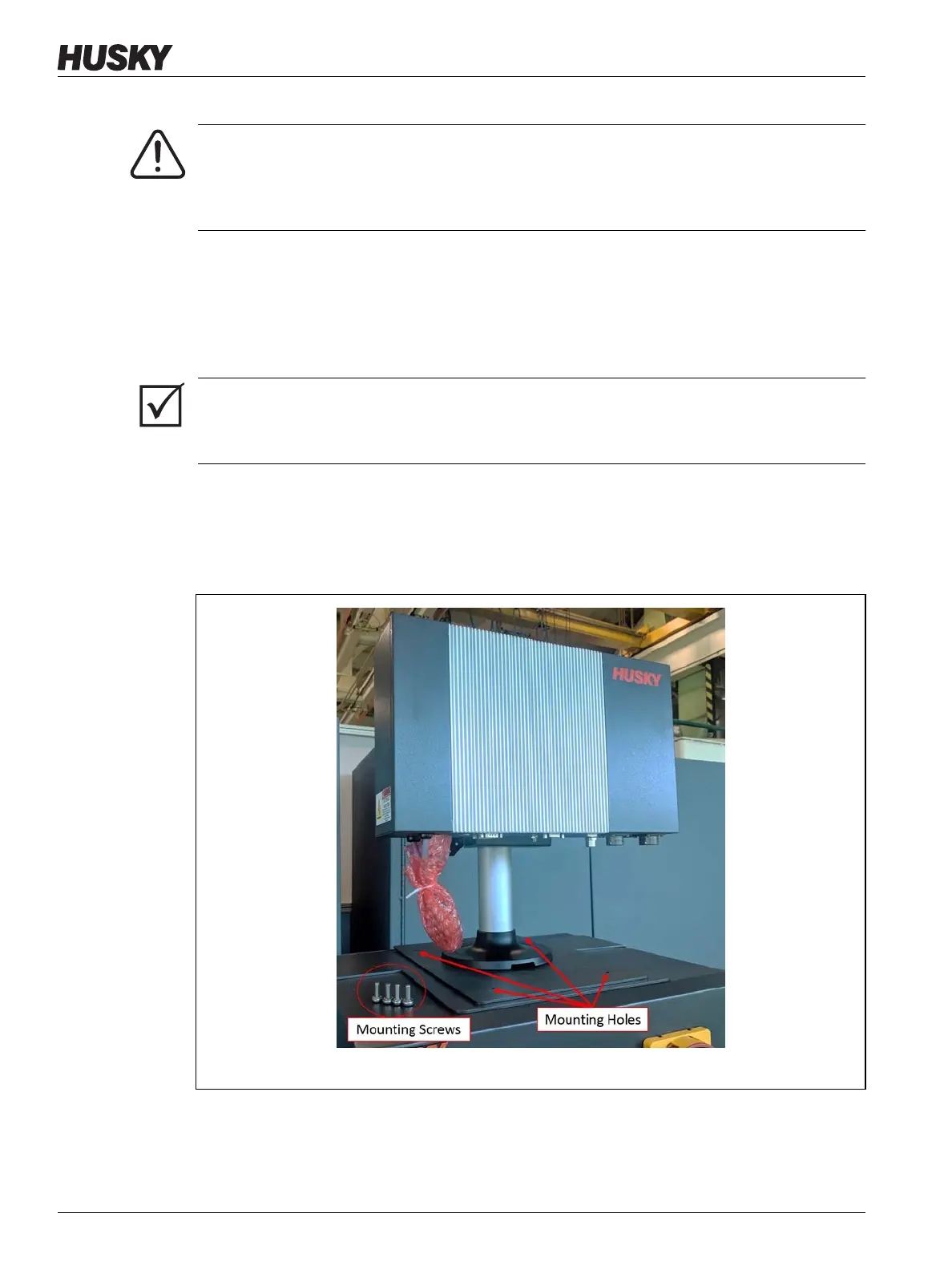
3. Unpack and place the MCU assembly with pedestal and mounting base on top of the
controller mainframe.
4. Make sure that the mounting holes in the base align with those in the top of the
mainframe. Refer to Figure 15-31.
5. Use a #4 Phillips screwdriver to install the supplied four M6 metric screws through the
mounting holes on the MCU base plate into the top of the mainframe.
NOTE: This step will require a screw driver short enough to clear the MCU located above
the two back mounting screws. Refer to Figure 15-32.
WARNING!
Electrical and mechanical hazard- risk of death, serious injury and/or damage to the
equipment. Turn off all power to the system and disconnect it completely from the
main input power.
IMPORTANT!
The MCU with pedestal and mounting base should be orientated so that the heatsink on the
MCU faces towards the front of the controller.
Figure 15-31 Alternative Mounted Operator Interface - Mounting Holes