v 1.0 — February 2020 Altanium Matrix5
222 Install the Alternative Mounted Operator Interface
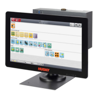
7. Connect the Touchscreen Signal cable connector, Touch Monitor Video cable connector
and Touch Monitor Power cable connector to the Touch Screen connector, LCD 12 VDC
connector, and VGS connector on the bottom of the MCU. Refer to Figure 15-34.
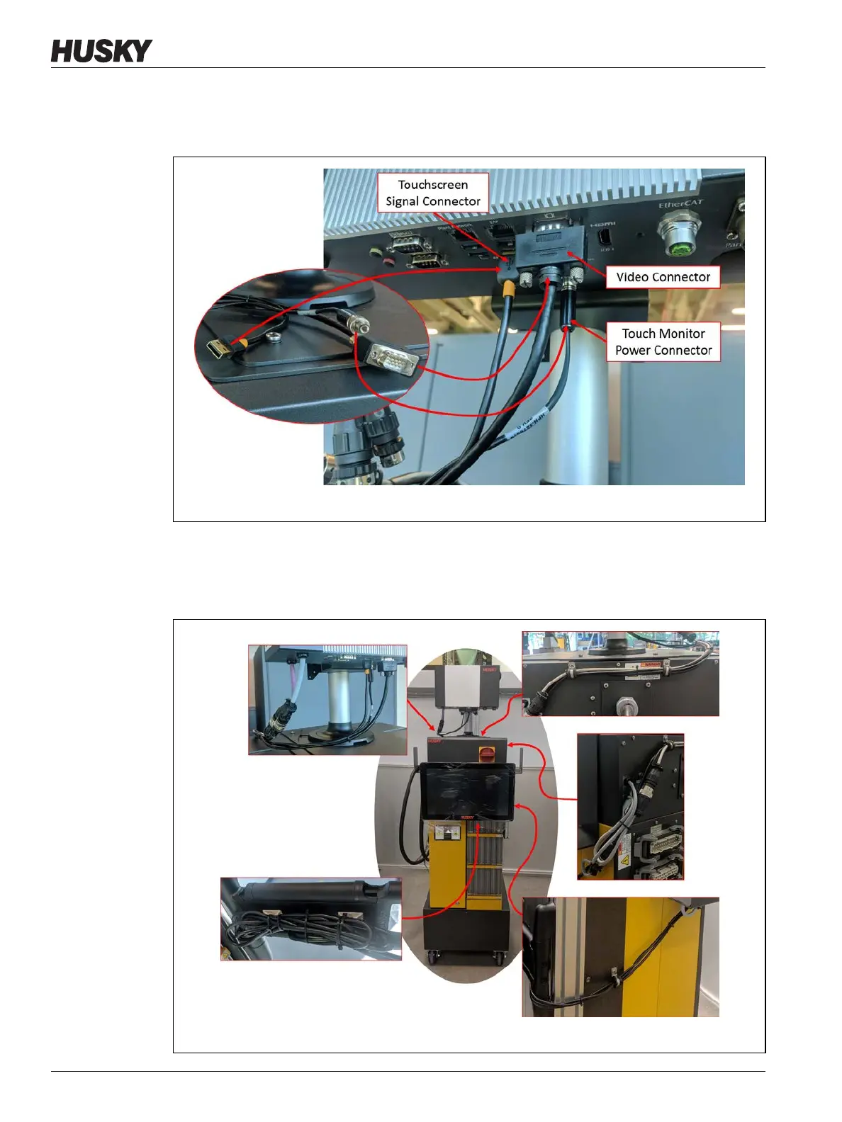
8. Use tie wraps to collect the lengths of cables between the touch monitor, controller
mainframe, and MCU. Make sure that all wires are away from pinch points and that there
is enough service loop to let the touch monitor and swing arm move freely. Refer to
Figure 15-35.
Figure 15-34 Touchscreen Signal, Monitor Video, and Monitor Power Cables
Figure 15-35 Attach Tie Wraps to Cables