115
A0801600-0001
WARNING / AVERTISSEMENT / AVISO
!
fi g. 8.34
fi g. 8.35
8 - A
Installation
Outriggers used at the top position can be installed either from the front or the back of
the motorized unit or the bridge.
In a confi guration where 63" (160 cm) outriggers are used at the top position only, the
maximum width of planking allowed is three planks. In a confi guration where 63" (160 cm)
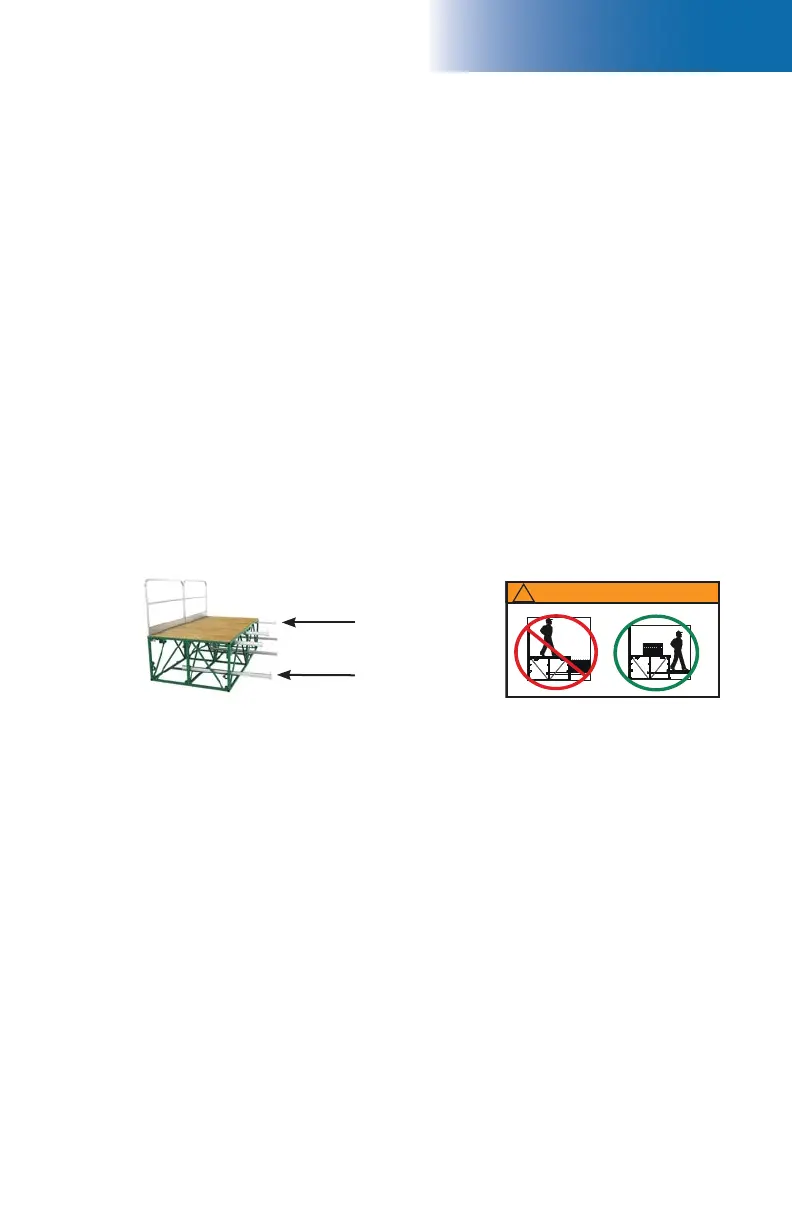
outriggers are used at both the top and bottom position (fi g. 8.34), the maximum width of
planking allowed at the top position is two planks. Refer to the Outrigger Selection table
and the planking confi guration guidelines on p. 111 for more information.
Each outrigger installed at the top position has a maximum capacity of 265 lb (120 kg) and
can be used for workers and material.
(optional)
Outriggers
1- Remove the clevis pin and the plank stop pin (fi g. 8.17, p. 111) and slide the outrigger
in the top outrigger pockets on the motorized unit or the bridge, leaving no more than
21" (53,3 cm) protruding from the structure if bottom outriggers are installed, or no
more than 31" (78,7 cm) if there are no bottom outriggers installed. Replace the clevis
pin and the plank stop pin.
2- Once the planks are in place, push in each outrigger until the plank stop pin rests
snugly against the planks.
3- Secure the outriggers in place by tightening the outrigger pocket bolts to a torque of
30 lb-ft (41 N-m).
Outriggers – Top position
Outriggers – Bottom position
Outriggers used at the bottom position can be installed either from the front or the back
of the motorized unit or the bridge. Each outrigger at the bottom position can be used by
workers only (including personal tools and equipment). The bottom outriggers cannot
be used to store material, tools, equipment or to support any other load. In a confi guration
where 63" (160 cm) outriggers are used at the bottom position, the maximum width of
planking allowed is three planks. Refer to the Outrigger Selection table and the planking
confi guration guidelines on p. 111 for more information.
Installation
1- Remove the clevis pin and the plank stop pin (fi g. 8.17, p. 111). Slide the outrigger in
the bottom outrigger pockets on the motorized unit or the bridge, leaving no more than
31" (78,7 cm) protruding from the structure. Replace the clevis pin and the plank stop pin.
2- Once the planks are in place, push in each outrigger until the plank stop pin rests
snugly against the planks.
3- Secure the outriggers in place by tightening the outrigger pocket bolt to a torque of
30 lb-ft (41 N-m).
Outriggers at
top position
Outriggers at
bottom position