117
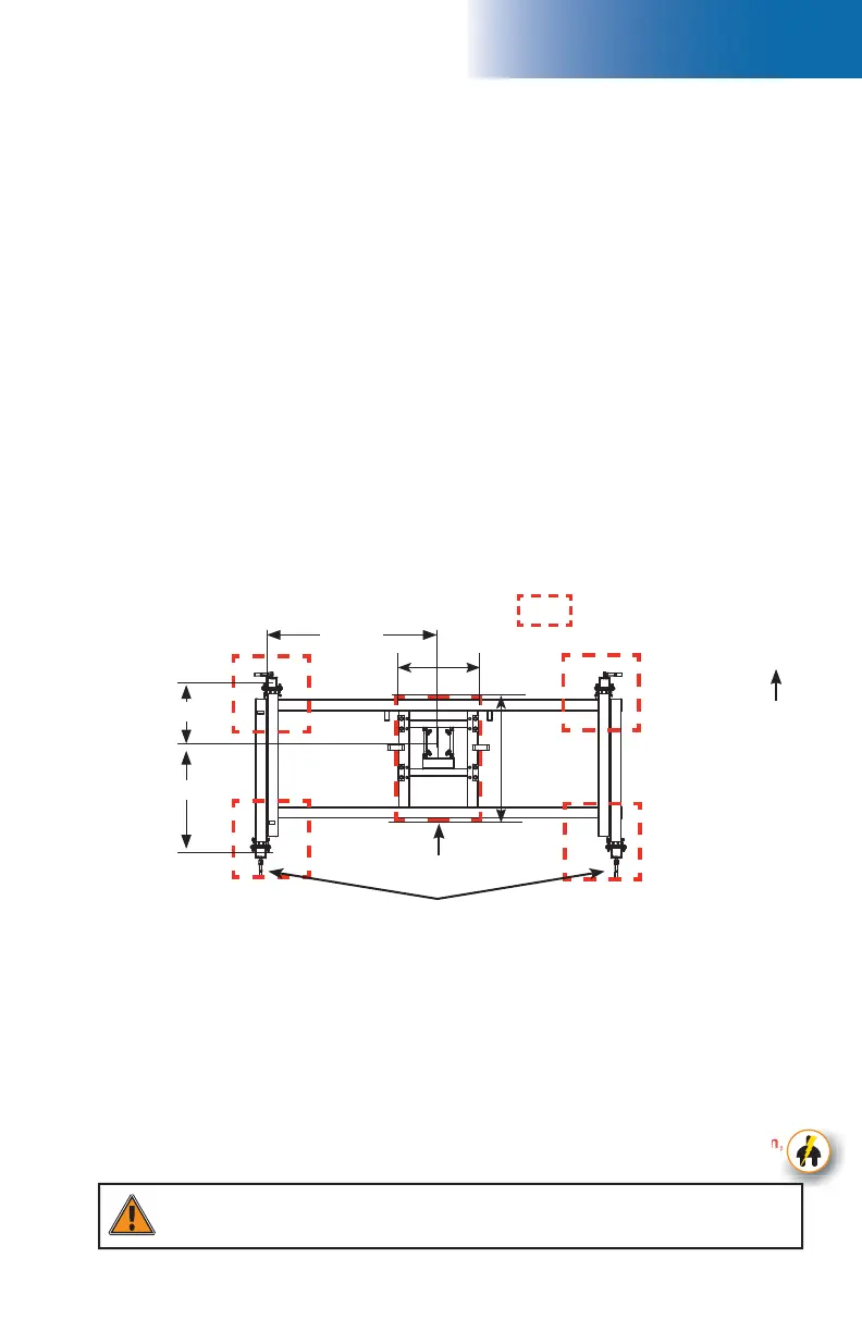
fi g. 8.39
31 7/8" (81 cm)
57 1/8" (145 cm)
91" (231 cm)
*
*
42"(107 cm)
63"
(160 cm)
8 - A
Mandatory cribbing areas
Central cribbing area
Cribbing under base jacks
Adapter Base for Freestanding Installation
(optional)
The optional adapter base for freestanding installation is used when an F2 Series setup requires
a freestanding confi guration. Freestanding F2 Series confi gurations are only allowed for
linked standard single unit installations. For the defi nition of a standard installation, refer
to p. 20 of the Motorized Unit section.
The weight of the adapter base (2500 lb or 1134 kg) must be considered in the loads applied
on the support surface. Refer to the Minimum Bearing Surface Capacities table, fi g. 1.21,
p. 16 for guidance.
Installation of the motorized unit on the adapter base
Installation of the adapter base
1- Make sure the adapter base is installed properly, as described in the installation instructions
above.
2- Make sure that there is one mast section installed on the motorized unit and that the mast
head is in place.
3- Using a rough terrain forklift or a crane, support the motorized unit using the shackle located
on top of the mast head. For instructions on lifting the motorized unit, refer to p. 131 of
the Transport, Storage and Maintenance section.
If an electrical unit is used, it is important to lift and move it with extreme precaution,
making sure the power cable remains clear of obstacles and is never too taut.
1- Installation must be carried out by qualified erectors/dismantlers under the
supervision of a competent person, in accordance with all applicable local regulations.
2- In reference to the plan/layout drawing, make sure that all the components required are
available. Establish the position of the adapter base, determine if there are obstacles
and what are the cribbing requirements.
3- Before installing the adapter base, determine where the cribbing under the base and
jacks will rest (see fi g. 8.39). Use the Authorized Height for a Freestanding Installation
with Adapter Base table on p. 118 of this section as a guide to determine the appropriate
extension of the base outriggers and the location of cribbing.
The bearing surface under the cribbing must be level, clear of debris and have the proper
bearing capacity (see the Minimum Bearing Surface Capacities table on
p. 16). Should
the actual bearing capacity be inferior to the values in the table, please seek instructions
and recommendations from the distributor/service center. It is important to note that the
jacks on the adapter base are designed to level the motorized unit and must not be
used to support the load nor the motorized unit.
To wall
*
Distances will vary according to the length of base outrigger extension required for the installation. Refer to the
Authorized Height for a Freestanding Installation with Adapter Base table, on p. 118 of this section.
WARNING
When using access stairs on a setup using an adapter base for freestanding
installation, it is important to install an additional stair extension.