88
1 32
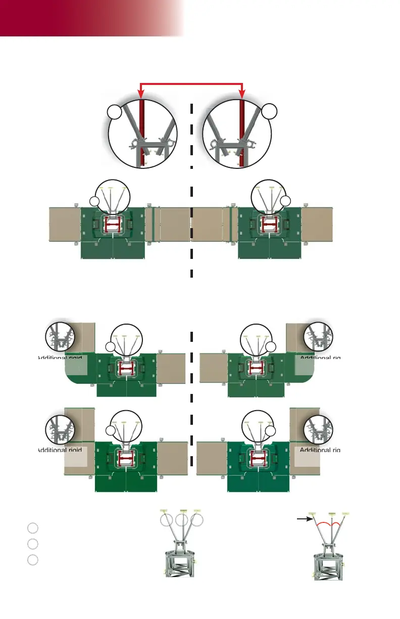
25° 25°
fi g. 6.12
fi g. 6.13
A
B
fi g. 6.14
6 - M M T
Mast Ties
Angle of installation of
mast ties
Recommended order of installation:
Perpendicular mast tie to be
installed fi rst
Opposite angled mast tie to be
installed second (angled at 25°)
Third mast tie to tighten the tie
installation (angled at 25°)
Cantilever end Cantilever end
Location of perpendicular mast ties according to confi guration
Additional rigid
dual clamps
must be installed
Additional rigid
dual clamps
must be installed
Multiple units confi gurations (with bearing bridge)
Location of perpendicular mast ties
Swivel bridge confi gurations
Front extension confi gurations
Swivel bridge
installed on this
side
Extension bridge
installed on this side
Perpendicular mast ties
shown in red for illustration
purposes only
1
2
3
Swivel bridge
installed on this
side
Extension bridge
installed on this side
Applies to all multiple units confi gurations (with bearing bridge) used with or without equipment or
accessories.
A
B
A
B
A
B
Additional rigid
dual clamps
must be installed
Additional rigid
dual clamps
must be installed
Each type of confi guration shown below requires the installation of additional rigid dual
clamps. Refer to p. 89 of this section for more information about the installation of
additional rigid dual clamps.
Single unit confi gurations