99
2000 lb
907 kg
2000 lb
907 kg
500 lb
227 kg
1000 lb
454 kg
2000 lb
907 kg
fi g. 6.6
fi g. 6.8
fi g. 6.7
fi g. 6.9
2000 lb
907 kg
500 lb
227 kg
2000 lb
907 kg
1000 lb
454 kg
2000 lb
907 kg
700 lb
318 kg
300 lb
136 kg
300 lb
136 kg
1000 lb
454 kg
500 lb
227 kg
2000 lb
907 kg
15' (4,6 m)
10' (3 m)
Total 1300 lb
590 kg
Total 1500 lb
680 kg
Total 2000 lb
907 kg
fi g. 6.10
fi g. 6.11
7 - L C
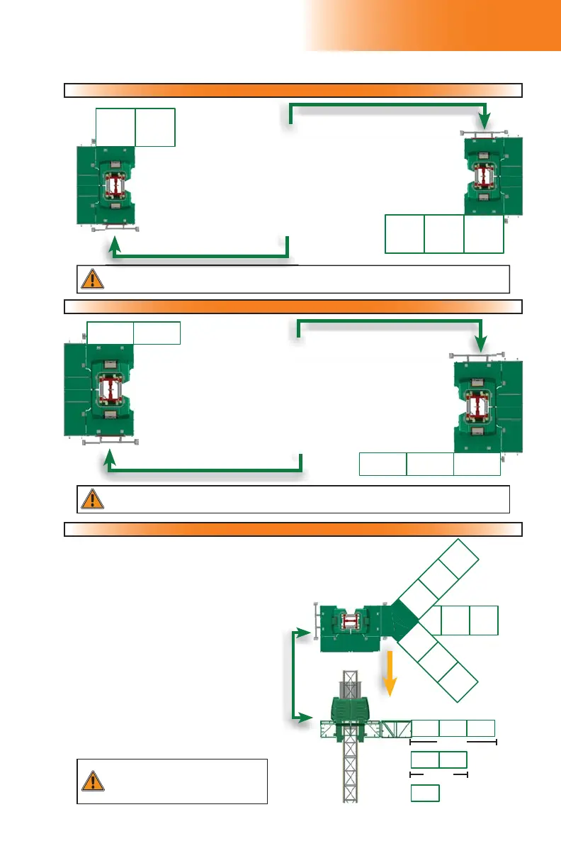
WARNING
The use of weather protection is
NOT ALLOWED for swivel bridge
installations.
WARNING
The use of weather protection is
NOT ALLOWED for forward extension installations.
WARNING
The use of weather protection is
NOT ALLOWED for forward extension installations.
Forward extension installation using a standard bridge (linked or unlinked)
Forward extension installation using a standard bridge (linked or unlinked)
Load Capacities
At this end, it is mandatory to install a bridge. The only bridge
confi gurations allowed at this end are the following:
Any cantilever confi guration (see p. 95 for a linked cantilever or p. 97
for an unlinked cantilever)
— OR —
any bearing bridge confi guration (see p. 96 for a linked
confi guration or p. 98 for an unlinked confi guration)
— OR —
any forward extension confi guration shown in this chart.
NO CONFIGURATION OTHER THAN THOSE
ABOVE ALLOWED AT THIS END
Forward extension installation using a multi purpose bridge (linked or unlinked)
Forward extension installation using a multi purpose bridge (linked or unlinked)
At this end, it is mandatory to install a bridge. The only bridge
confi gurations allowed at this end are the following:
Any cantilever confi guration (see p. 95 for a linked cantilever or
p. 97 for an unlinked cantilever)
— OR —
any bearing bridge confi guration (see p. 96 for a linked
confi guration or p. 98 for an unlinked confi guration
— OR —
any forward extension confi guration shown in this chart.
NO CONFIGURATION OTHER THAN THOSE
ABOVE ALLOWED AT THIS END
View from top
Rear view
At this end, it is mandatory to install a
bridge.
The only bridge configurations
allowed at this end are the following:
Any cantilever configuration (see p. 95 for
a linked cantilever or p. 97 for an unlinked
cantilever)
— OR —
any bearing bridge confi guration (see p. 96
for a linked confi guration or p. 98 for an
unlinked confi guration
— OR —
any swivel bridge confi guration shown in
this chart.
NO CONFIGURATION OTHER THAN THOSE
ABOVE ALLOWED AT THIS END
Swivel bridge installation – Single unit (0-45 degrees) – (linked or unlinked)
Swivel bridge installation – Single unit (0-45 degrees) – (linked or unlinked)