26
21
3
1 2
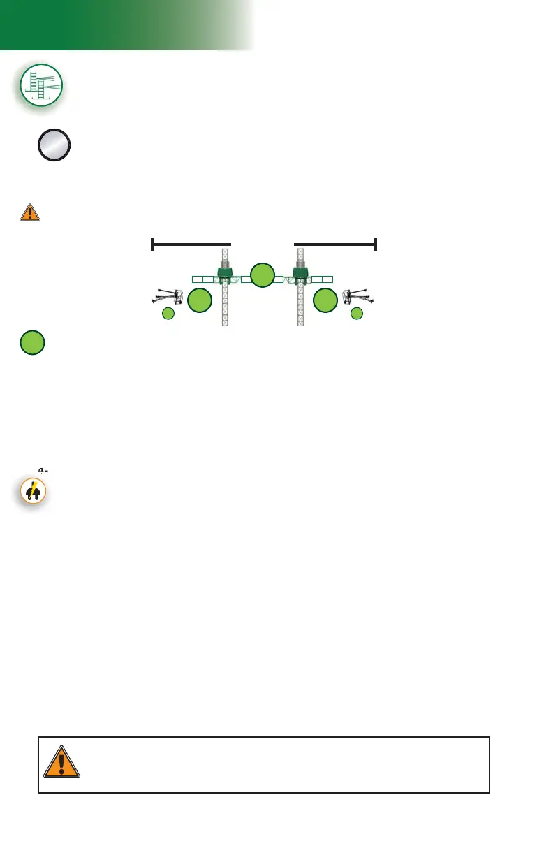
fi g. 1.33
1 - M U
Setup and Confi gurations
Multiple units installation with mast ties – pre-installation
(requires two twin mast adapters – sold separately)
C
The following installation steps can be used for standard and non-standard
confi gurations of tied installations with multiple units linked by a bearing
bridge. For more information about the defi nition of a standard confi guration, refer to
p. 20 of this section. For more information about the combined use of equipment
and accessories in an installation, refer to the tables for the combinations allowed or
restricted in linked and unlinked confi gurations on p. 17 and p. 18 of this section.
Top of work
1
Installation of the fi rst motorized unit
1- Prepare the fi rst motorized unit and the area where the setup will be installed as
described in the general guidelines starting on p. 17.
2- Lift and align the base of the motorized unit with the face of the work and lower it into position.
3- Using the jacks on the lateral base extensions, level the mast on both its front and
side axis, then, if required, use metal shims to make sure that the base sits squarely
and level on the cribbing.
Positioning the fi rst motorized unit
4- If the unit used in the setup is an electrical unit, select a power cable appropriate for the
height of the mast. Refer to the Power Cable Selection Chart on p. 72 of the Power
Pack and Operating Components section for help with the selection of the power cable.
Make sure that the overall length of the cable is suffi cient for the installation (height of
mast, distance from power source, acceptable overall slack in cable).
5- Install and connect the power cable. This installation must be performed by a
certifi ed electrician. For instructions on the installation of the power cable, refer
to the startup preparation instructions on p. 71 of the Power Pack and Operating
Components section.
Connection of the unit and control panel to the power supply (electrical unit)
Installation of the fi rst cantilevers
6- Using any appropriate lifting device such as a crane or a rough terrain forklift, install
only one 5' (1,5 m) bridge on each side of the mast. Refer to the Bridges section
on p. 50 for instructions on bridge installation.
Verifi cation of limit switches and screen alerts
7- Pull out the emergency stop button and unlock the display screen. Make sure that the
appropriate confi guration options have been selected (
F4) on the display screen. For
information about the functions and alerts of the control panel, refer to p. 77 of the
Control Panel section.
8- Inspect the strobe under the main frame and make sure it is working properly.
9- Review the screen alerts and perform a verifi cation of the limit switches. For instructions
on how to verify the limit switches, refer to p. 48 of the Safety Devices section.
WARNING
It is recommended that two persons handle all rise and descent operations of each motorized
unit and that at least one of those two persons is a qualifi ed operator. It is important to
coordinate the motion of motorized units linked by a bearing bridge to keep the structure as level
as possible.
Pre-installation must be performed in a linked confi guration only. Once pre-installation is
complete, refer to p. 34 of this section for instructions on how to split a motorized
unit, if required and allowed.