67
fi g. 3.63
fi g. 3.64
fi g. 3.65
fi g. 3.66
fi g. 3.67
fi g. 3.68
fi g. 3.69
fi g. 3.70
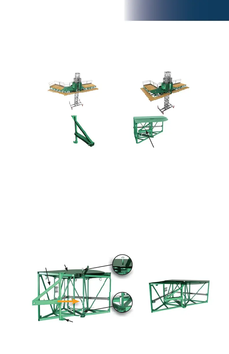
3 - B
Outrigger
support
assembly
Swivel
bridge
Top pivot pin
Bottom pivot pin
Bottom
(forked) plate
Bridges
Swivel Bridge Outrigger Support Assembly
The outrigger support assembly is designed to be used as a plank support structure in
swivel bridge back confi gurations (0 to 45° and 90°).
0 to 45° confi gurations 90° confi guration
Outrigger support
assembly
Outrigger support assembly
stored inside swivel bridge
(transport position)
(optional)
Installation
1- Make sure that the end of the swivel bridge that is not bolted to the main frame (pivoting end,
fi g. 3.53, p. 65) is supported so the two halves of the swivel bridge remain together.
2- Remove the lock bolt from the top pivot pin (fi g. 3.68). It is not necessary to remove
the lock bolt from the bottom pivot pin.
3- Lift out the top pivot pin until it clears the top part of the pivot structure and it is possible
to align the hole in the top plate of the outrigger support assembly. It is not necessary
to remove the pivot pin completely. Lift out the bottom pivot pin (fi g. 3.69) until it is
possible to insert the bottom plate around the pivot pin of the outrigger support assembly.
4- Slide in the bottom plate of the outrigger support assembly around the bottom pivot pin
and align the hole of the top plate with the top pivot pin. Insert the pivot pin.
5- Tighten the top lock bolt to secure the top pivot pin.