66
fi g. 3.58
fi g. 3.60
fi g. 3.61
fi g. 3.62
fi g. 3.59
g.
g. 3.62
3 - B
Bridges
3- Make sure that the end of the swivel bridge that is not bolted to the main frame
(pivoting end, fi g. 3.53, p. 65) is supported so the two halves of the swivel bridge
remain together.
4- Remove the lock bolt from the top pivot pin (fi g. 3.55, p. 65). It is not necessary to
remove the lock bolt from the bottom pivot pin.
5- Lift out the top pivot pin until it clears the top part of the pivot structure and it is possible
to align the hole in the top plate of the counterweight adapter. It is not necessary to
remove the pivot pin completely. Lift out the bottom pivot pin (fi g. 3.56, p. 65) until
it is possible to insert the bottom plate (forked) of the counterweight adapter around
the pivot pin.
6- Slide in the bottom plate of the counterweight adapter around the bottom pivot pin and
align the hole of the top plate with the top pivot pin. Replace the top pivot pin.
Swivel Bridge Counterweight Adapter
(optional)
Installation (cont’d)
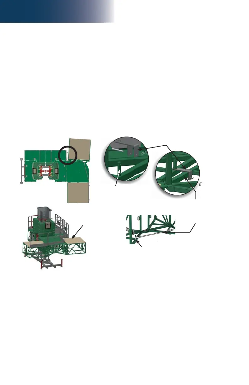
7- Make sure the counterweight adapter is slightly at angle, as shown in fi g. 3.58.
8- Locate the support pin on the side opposite to where the adjustment rod is located,
as shown in fi g. 3.62. Slide the lock bracket over the pin and a bottom chord of the
counterweight adapter. Secure the bracket in place using a clevis pin and a bow tie.
9- Replace the lock bolt of the top pivot pin and tighten to secure.
10- Bolt a standard 5' (1,5 m) bridge to the counterweight adapter as described in steps 1 and
2 of the installation instructions for a standard bridge, on p. 50 of the Bridges section.
11- Install forward cantilevers, as required and allowed (fi g. 3.53, p. 65). Refer to the
Load Capacities section on p. 94 for the number of bridges allowed in a confi guration.
12- Apply the counterweight on the installed bridge. For information on the type of
counterweight to apply, refer to p. 102 of the Load Capacities section.
13- Secure counterweight onto bridge structure and identify as counterweight not to be
moved or modifi ed.
Support pin for
adjustment rod
Counterweight
adapter installed at
angle
Adjustment rod
Use support pin on side
opposite to this one
Lock bracket
Bottom chord of
counterweight adapter