136
fi g. 9.16
fi g. 9.17
fi g. 9.13
fi g. 9.14 fi g. 9.15
9 - T, S M
USE CHECK MARK FOR EACH ENTRY VERIF IED. IF NECESSARY, TAKE CORRECTIVE ACTION BEFORE INSERTING CHECK MARK.
DAILY INSPECTION CHECKLIST
QUALIFIED USER/OPER ATOR (full name):
MOTORIZED UNIT SERIAL NUMBER:
MOTORIZED UNITS and ACCESSORIES
Each Hydro Mobile motorized unit and its accessories must be inspect ed daily or before every w orking shift, as well as weekly. These inspect ions must be carried ou t by a qualified user / operator. Use the
spaces below to monitor 6 days of the daily and weekly inspections. Use the Notes and Comments form to indicate any discrepancy or any item found to be not acceptable. Any d iscrepancy must be
reported and appropriate corrective action must be taken immediately. Corrective actions must be performed b y a qualified technician. "Qualified" means a person who, by possession of a recognized
degree, certificate or professional standing, or who by extensive knowledge, training and exp erience, has successfully de monstrated the ability to solve or resolve problems relating to the subject matter,
the work or the project. Only a qualified user/operator on the specific make and model of the Hydro Mobile equipment is allowed to perform daily and weekly maintenance inspections and only a qualified
technician on the specific make and model of the Hydro Mobile equipment is allowed to perform repairs on Hydro Mobile units. These inspections and rep airs must be performed accord ing to the
guidelines, instructions, warnings and methods set out i n the owner’s manuals and Hydro Mobile training courses.
Daily and weekly inspections must be performed by a qualified user/operator (see above).
SERIAL NUMBER (if applicable):
Access stairs, ramps and door are clear of any obstruction and in good condition.
All access panels are clear of material and equipment.
All safety guardrails are in position and doors are operational (no fall hazard). Mast guards are in position and secure.
An evacuation plan specific to the job site is available to all workers and a legible copy of the owner’s manual is in the too l box.
Construction traffic is controlled on and a round job site (proper barriers installed).
If the work platform is accessed from inside the building or off a scaffold stair tower, transfer is safe and free from obstruction.
Minimum clearance from overhead power lines is maintaine d according to local regulation.
On special façade shapes, cross box kits, fa ce guardrails and plank guardrails are properly installed and secure.
Perimeter of setup is safe and delimited (warning tape, co ncrete blocks).
Setup and installation meet the requirements prescribed by owner’s ma nual or approved engineering drawing.
The platform clears all obstacles (building, balc onies, etc.) and can be raised or lowered.
Work and circulation areas on the platform are clear of any obstruction.
SERIAL NUMBER (if applicable):
Base is level and cribbing under pedestal has not moved.
Rubber buffers on the base are in place and in good c ondition.
SERIAL NUMBER (if applicable):
MOTORIZED UNIT – COMPONENTS
Control panel is working properly and displays no alar m.
Emergency stop has been verified and is working properly. IGNITION MUST BE TURNED OFF when the unit is not in operation.
Gasoline and engine oil levels are appropriate or have been reple nished. Air filter has been verified and is in good condi tion or has been replaced, if
necessary.
Hydraulic oil level has been verified and hydraulic tank has been replenished, if required, with oil recommended by Hydro Mobile.
Inspect trolley structure for any welding defects, damaged parts and excessive rust or corrosion.
Lifting mechanism is clear of debris (mortar, maso nry material, etc.) and shows no signs of exces sive wear.
Limit switches, proximity switches (top, top final, bottom, bottom final) and door sensors have been checked and are wo rking properly (on both sides on
model F300).
Motorized unit structure has been inspected and shows no signs of damage or distortion.
On an electrical unit, the power cable has been inspected and shows no signs of damage. Input power is adequate and phases are in sync.
On an electrical unit, the routing of the power cable is free from o bstruction and the cable recoils properly.
Racks and gears must be greased at least once a week from top of setup to base level using open-gear lubricant recommended by Hydro Mobile.
Lubrication schedule must be adapted to application (runtime ho urs, specific conditions, etc.). Refer to the owner’s manual for complete instructions on
the appropriate lubrication method.
SERIAL NUMBER (if applicable):
MOTORIZED UNIT – SAFETY DEVICES
Overspeed safety device (safety brake) mec hanism has been inspected and shows no apparent signs o f defect, and is free of grease or any other
substance. Grease must never be applied on the components of the overspeed safety device. (WEEKLY)
With the setup at 10' (3 m) above the bearing surface and without any loads on the platform, testing of the emergency descent system has been
performed (on installation and subsequently once a week) to make sure it is operating normally. (WEEKLY)
F100 - F200 - F300 and F-TP
MOTORIZED UNITS and ACCESSORIES
FREQUENT INSPECTION CHECKLIST
AUTHORIZED DEALER NAME and ADDRESS:
USER/OWNER NAME and ADDRESS:
NAME of QUALIFIED TECHNICIAN:
MOTORIZED UNIT MODEL and SERIAL NUMBER:
USE CHECK MARK FOR EACH ENTRY VERIF IED. IF NECESSARY, TAKE CORRECTIVE ACTION BEFORE INSERTING CHECK MARK.
Frequent inspections must be performed by a qualified technician (see above).
Each Hydro Mobile motorized uni t and its accessories must be submitted to a frequent inspection. Use the spaces below to monitor inspections that need to be performed every three months. Use the
Notes and Comments form to indicate any discrepancy o r any item found to be not acceptable. Any discrepancy must be reported and appropriate corrective act ion must be taken immed iately. Corrective
actions must be performed b y a qualified technici an. "Qualified" mean s a person who, by p ossession of a recognized degree, certificate or professional standing, or who by extensive knowledge, training
and experience, has successfull y demonstrated the abili ty to solve or resolve problems relating to the subject matter, the work or the project. Only a qualified person on the specific make and model of the
Hydro Mobile equipment is allowed to perform maintenance inspections and repairs on Hydro Mobile units according to the guidelines, instructions, warning s and methods set out in the ow ner’s manuals
and Hydro Mobile training courses. All inspection steps included in the daily inspection checklist must be performed before the frequent inspection steps.
It is recommended to use rep lacement parts manufactured b y or recommended by Hydro Mobile. The use of substitution parts could not only void the warranty covering this motorized uni t and its
components but cause seriou s damages that could l ead to injury or death. It is recommended to replenish and grease components only with fluids and lubricants recommended by Hydro Mobile.
SERIAL NUMBER (if applicable):
If the work platform is accessed from inside the building or off a scaffold stair tower, transfer is safe and free from obstruction.
SERIAL NUMBER (if applicable):
Inspect bottom and bottom final limit sensor trigger (LEFT) (F 300 model only).
Inspect bottom and bottom final limit sensor trigge r (RIGHT).
Inspect jack (4x or 8x, as applicable) gears and mechanism. Grease jack mechanism, if necessary.
Inspect pedestal extension structure for any welding defects, damaged parts and excessive rust or c orrosion (LEFT).
Inspect pedestal extension structure for any we lding defects, damaged parts and excessive rust or c orrosion (RIGHT).
Inspect pedestal structure for any welding defec ts, damaged parts and excessive rust or corro sion.
Inspect rubber buffers on the base. Replac e if damaged.
SERIAL NUMBER (if applicable):
MAIN FRAME STANDARD - LEFT (F100-F200)
Check all guardrails, guardrail attachment hardware and doors for any welding defects, damaged parts and excessive rust or corrosion.
Inspect integrity of main frame access door and locking mechanism.
Inspect main frame structure for any welding defects, damaged parts and excessive rust or corrosion.
SERIAL NUMBER (if applicable):
MAIN FRAME HYDRAULIC - LEFT (F300)
Adjust engine RPM at full throttle and idle speed as per technical procedure.
Check all guardrails, guardrail attachment hardware and doo rs for any welding defects, damaged parts and exces sive rust or corrosion.
Check all hydraulic hoses and fittings for any leaks or signs of wear.
Check condition of hydraulic pressure filter (2x).
Check condition of the hydraulic return filter and replac e, if necessary.
Clean battery connections and perform battery load test a s per technical procedure.
Inspect electrical wiring and connection to all se nsors and connectors.
Inspect integrity of main frame access door and locking mechanism.
Inspect main frame structure for any welding defec ts, damaged parts and excessive rust or corro sion.
Inspect operation of choke solenoid and return.
Inspect throttle cable and chec k adjustment.
Perform charging system test on Honda engine as per technical pro cedure.
Test operation of oil cooler fan as per technical procedure.
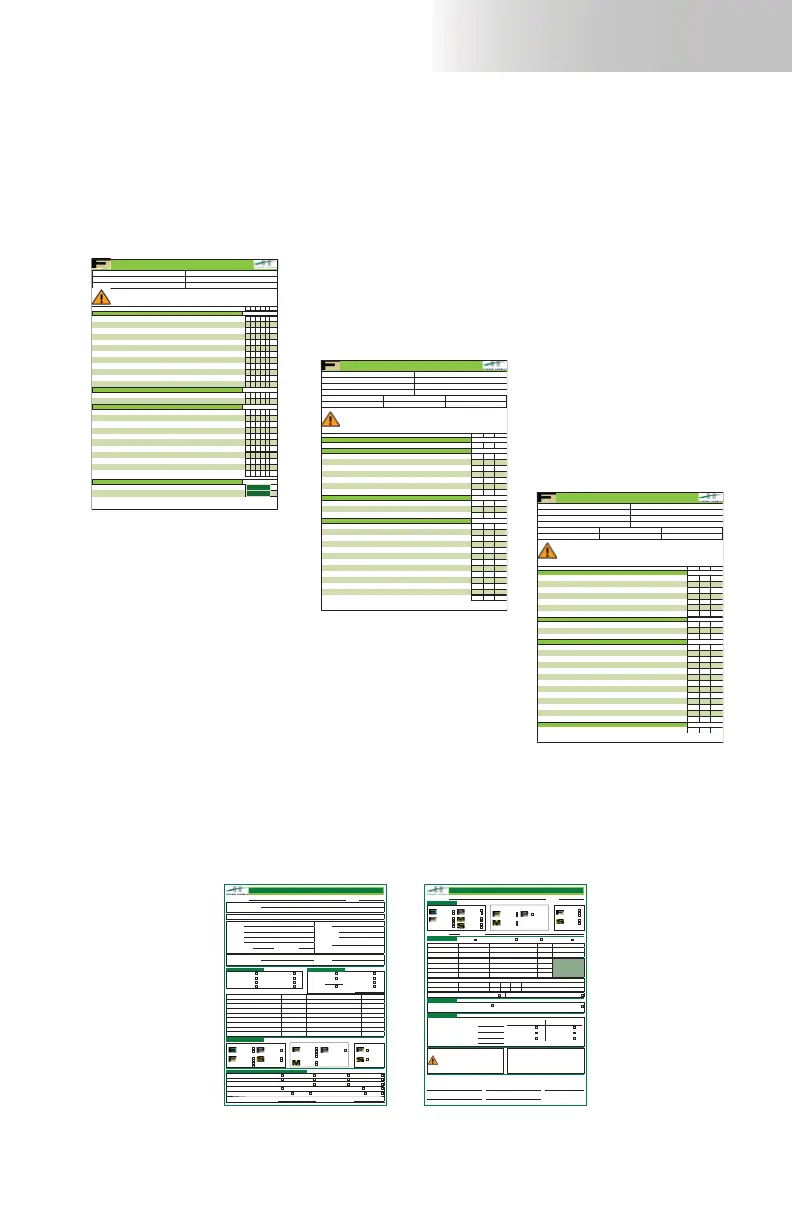
Daily inspection checklist
Frequent inspection checklist
Inspections and Maintenance
F100 - F200 - F300 and F-TP
MOTORIZED UNITS and ACCESSORIES
ANNUAL INSPECTION CHECKLIST
AUTHORIZED DEALER NAME and ADDRESS:
USER/OWNER NAME and ADDRESS:
NAME of QUALIFIED TECHNICIAN:
MOTORIZED UNIT MODEL and SERIAL NUMBER:
Annual inspections must be performed by a technician qualified (see above).
USE CHECK MARK FOR EACH ENTRY VERIFIED. IF NECESSARY, TAKE CORRECTIVE ACTION BEFORE INSERTING CHECK MARK.
Each Hydro Mobile motorized unit and its accessories must be submitted to an annual inspection. Use the spaces below to monitor inspections that need to be performed every year. Use the N otes and
Comments form to indicate a ny discrepancy or any item found to be not acceptable. Any discrepancy must be reported and a ppropriate corrective actio n must be taken immediat ely. Corrective actions
must be performed by a qualified technician. "Qualified" means a person who, by possession of a recognized deg ree, certificate or profession al standing, or who by extensive knowledge, training and
experience, has successfully demo nstrated the ability to solve or resolve proble ms relating to the subj ect matter, the work or the pro ject. Only a qualified person on the specific make and model of the
Hydro Mobile equipment is allowed to perform maintenance inspections and repairs on Hydro Mobile units according to the guidelines, instructions, warnings and methods set out in the owner’s manuals
and Hydro Mobile training courses.
It is recommended to use rep lacement parts manufactured b y or recommended by Hydro Mobile. The use of substitution parts could not only void the warranty covering this motorized unit and its
components but cause serious damages that could lead to injury or death. It is recommended to repl enish and grease compon ents only with fluids and lubricants recommended by Hydro Mobile.
SERIAL NUMBER (if applicable):
Inspect bottom and bottom final limit sensor trigger (LEFT) (F 300 model only).
Inspect bottom and bottom final limit sensor trigge r (RIGHT).
Inspect jack (4x or 8x, as applicable) gears and mechanism. Grease jack mechanism, if necessary.
Inspect pedestal extension structure for any welding defects, damaged parts and excessive rust or c orrosion (RIGHT).
Inspect pedestal extension structure for any we lding defects, damaged parts and excessive rust or c orrosion (LEFT).
Inspect pedestal structure for any welding defec ts, damaged parts and excessive rust or corro sion.
Inspect rubber buffers on the base. Replac e if damaged.
SERIAL NUMBER (if applicable):
MAIN FRAME STANDARD - LEFT (F100-F200)
Check all guardrails, guardrail attachment hardware and doors for any welding defects, damaged parts and excessive rust or corrosion.
Inspect integrity of main frame access door and locking mechanism.
Inspect main frame structure for any welding defects, damaged parts and excessive rust or corrosion.
SERIAL NUMBER (if applicable):
MAIN FRAME HYDRAULIC - LEFT (F300)
Adjust engine RPM at full throttle and idle speed as per technical pr ocedure.
Check all guardrails, guardrail attachment hardware and doo rs for any welding defects, damaged parts and exces sive rust or corrosion.
Check all hydraulic hoses and fittings for any leaks or signs of wear.
Clean battery connections and perform battery load test a s per technical procedure.
Inspect electrical wiring and connection to all se nsors and connectors.
Inspect integrity of main frame access door and locking mechanism.
Inspect main frame structure for any welding defec ts, damaged parts and excessive rust or corro sion.
Inspect operation of choke solenoid and return.
Inspect throttle cable and check adjustment.
Perform charging system test on Honda engine as per technical pro cedure.
Replace the hydraulic pressure filter (2x).
Replace the hydraulic return filter.
Test operation of oil cooler fan as per technical procedure.
SERIAL NUMBER (if applicable):
MAIN FRAME HYDRAULIC - RIGHT
Adjust engine RPM at full throttle and idle speed as per technical procedure.
Copies of the job survey checklist and the handover checklist shown below can be obtained
by contacting the distributor/service center or the Hydro Mobile technical support team or
downloaded directly from the Hydro Mobile website at www.hydro-mobile.com.
Annual inspection checklist
F300 – 460V
F200 – 460V
F300 – 600V
F200 – 600V
F300 – 460V
F200 – 460V
F300 – 600V
F200 – 600V
240V
400V
230V
400V
Power pack
bridge
24' (7,3 m)
14' (4,3 m)
Crane available for Erecting Repositioning Dismantling Loading / unloading
Forklift available for Erecting Repositioning Dismantling Loading / unloading
Installation to be erected / dismantled by Hydro Mobile Hydro Rents Dealer
Installation to be erected / dismantled by user User installers are appropriately qualifi ed
YES NO
Erector / dismantler training required
YES NO
User / operator training required
YES NO
Number of E&D training attendees Number of U/O training attendees
JOB SURVEY – JOB HAZARD ANALYSIS
Project Name: Date:
Series to be used for project
ELECTRI C-POWERE D GA S-POWERE D TRANSPORT PLATFORM
Project address
City State/Province
Estimated start date Estimated duration
WEEKS
Company Contact
Address Contact phone
Contact email
City
Notes
State/Province Zip/Postal code
Phone Fax
General contractor Contact
Phone Contact phone
Brick Roofi ng
Block / stone Material only
Stucco Personnel / material
Glazing Other
Scope of work
Steel frame Wood frame
Concrete Post tension cables
psi Balcony slab
Load bearing masonry Other
(specify)
Building / structure details
Height of building
FT
M
Number of bearing bridges
Number of motor units Maximum cantilever length
FT
M
Number of repositions Outrigger support
Number of hoists Length of planking
FT
M
Number of swivel bridges Number of MPIs or planked corner returns
Required capacity
LB
KG
Counterweight required
Total mast height
FT
M
Number of ties per mast (if tied)
Distance between tie levels
FT
M
Type of anchors (if tied)
Height of fi rst tie level
FT
M
Max travel distance above last tie level
MAST(S)
Available services and training levels
HMJAJHA0315
F300 – 480V
F200 – 480V
F300 – 600V
F200 – 600V
F300
F200
480V
600V
240V
400V
Power pack
bridge – 480V
24' (7,3 m)
14' (4,3 m)
240V
400V
480V
600V
240V
400V
Power pack
bridge – 600V
Single unit Multiple units
(bearing bridge)
Freestanding With mast ties
INSTALLATION HANDOVER SHEET
Project Name: Date:
Number of units: Serial numbers:
Series used for project
ELECTRIC-POWERED
GAS-POWERED
TRANSPORT PLATFORM
WARNING
To ensure safety at all times on a mast climbing work platform system,
bridges should not be loaded beyond their maximum rated weight capacities.
In addition, to prevent a mast climbing work platform system from stalling
because of an overload, maximum rated load capacities of the motorized
unit(s) should be observed. Overloading a mast climbing work platform
system could result in serious injury or death.
It is mandatory to refer to the load capacity charts located on the motorized
unit and included in the owner’s manual at all times.
NOTE
All assembly and operation instructions located on motorized units and bridges take precedence over information
contained in this manual. Should there be any discrepancies discovered throughout any published documentation
issued by Hydro Mobile or its authorized affi liates, the following order of precedence shall prevail:
1. Written documents issued by the Hydro Mobile Engineering department
2. Recall instructions
3. Assembly or operation instructions displayed on the motorized unit
4. Owner's manual
Any use of one or several Hydro Mobile motorized units, with or without accessories, in such a confi guration
or manner as not explicitly described in this manual is not allowed without the permission of Hydro Mobile Inc.
Progressive installation
If setup will be installed progressively, skip ties and anchors information
section
Complete installation
Mast ties must be installed to the top of the installation before the start of any
work
Method of installation
Ties and anchors
Maximum height
FT
M
Height of fi rst tie level
FT
M
Distance between tie levels
FT
M
Number of mast sections above last tie level
Anchor type Shelf angle
Mechanical expansion Welded
Mechanical screw Drilled
Chemical / resin Brick anchor
Details of installation
This motorized unit installation has been assembled following Hydro Mobile’s instructions and complies with applicable local regulations. The motorized unit(s)
and its (their) accessories have been submitted to all steps included in the daily inspection checklist recommended for Hydro Mobile motorized units and their
accessories. The installation has been tested and handed over in a fully functional, safe condition. This installation cannot be re-confi gured in any way without
the owner’s permission.
Installer signature Installer name (
IN PRINT
) Date of installation
Cantilever bridges Length Composition No. planks Counterweight
Left cantilever
FT
M
LB
KG
Right cantilever
FT
M
LB
KG
Bearing bridge(s) Length Composition No. planks
Bridge 1
FT
M
Bridge 2
FT
M
Bridge 3
FT
M
Length of corner returns
Left
FT
M
OMS
(Circle O for Outriggers, M for MPI or S for Swivel Bridge)
Right
FT
M
OMS
(Circle O for Outriggers, M for MPI or S for Swivel Bridge)
HMHS0315
Owner signature Owner name (
IN PRINT
)
GAS-POWERED
Load capacities must be compliant with Owner’s manual Load capacities must be compliant with approved layout
Samples of Checklists
Copies of the inspection and maintenance checklist shown below can be obtained by
contacting the distributor/service center or downloaded directly from the Hydro Mobile website
at www.hydro-mobile.com.