39
fi g. 1.52
1
2
1 - M U
Setup and Confi gurations
The following dismantling steps can be used for a multiple units confi guration
installed following method of installation “C”. Refer to p. 26 of this section
for more information about method of installation “C”.
Dismantling a multiple units installation with mast ties
C
1- Prepare the installation as described in the safety guidelines for dismantling an F2 Series
installation, on p. 36.
2- Bring the motorized units to base level and remove all loads from the platform.
3- With the units at base level, remove any installed equipment or accessory (such as
wider planking confi guration, swivel bridge, forward extension bridge, monorail, weather
protection, cantilever reinforcement cable retainer, etc.).
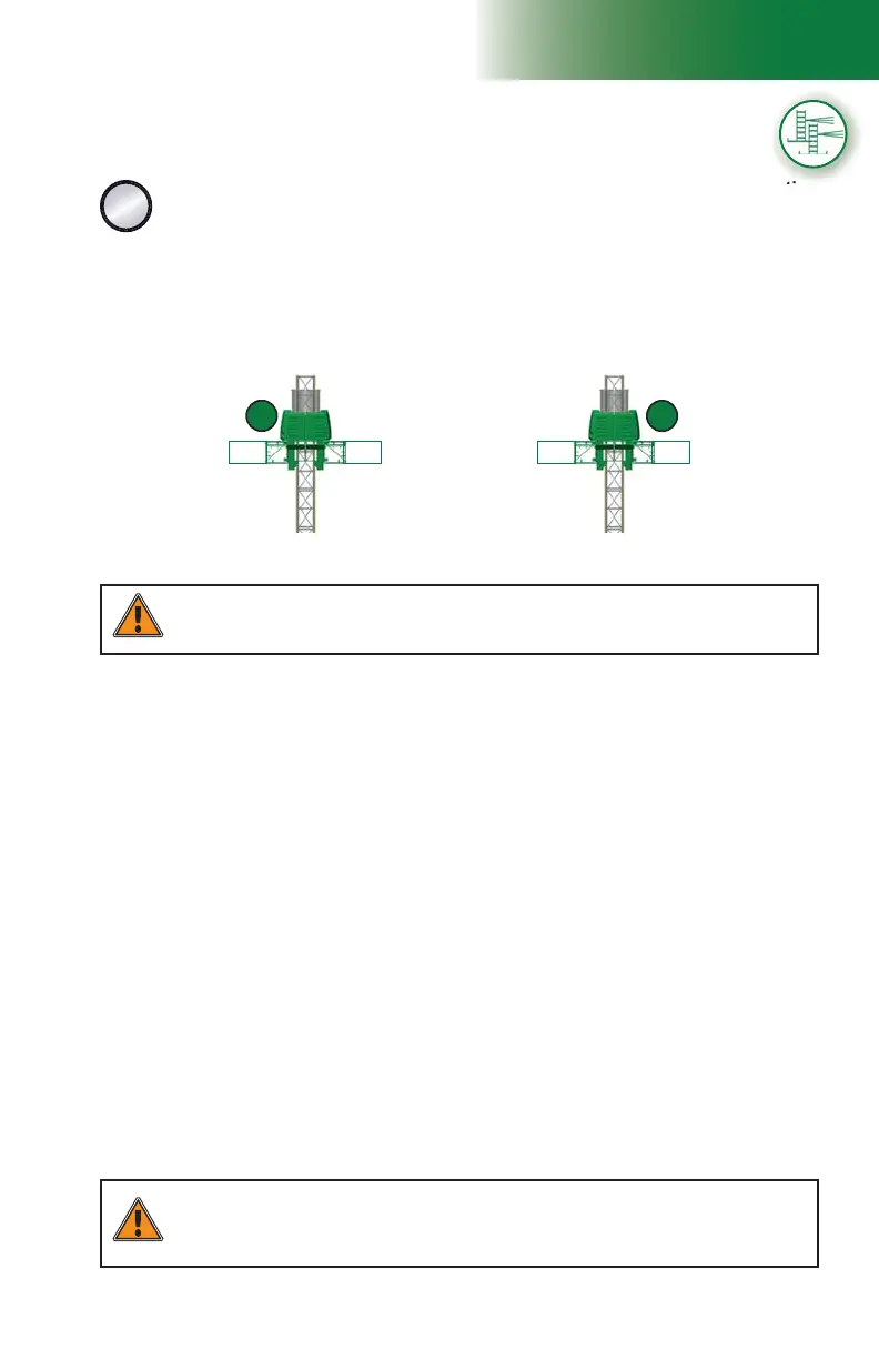
Bearing bridge
removed
Only one 5' (1,5 m) bridge
at each cantilever end
Only one 5' (1,5 m) bridge at
each cantilever end
2
WARNING
Before the start of dismantling operations of a setup installed following installation
method “C”, it is mandatory to uninstall any equipment, accessory or bridge, leaving only
one 5' (1,5 m) bridge attached at each cantilever end of the motorized unit.
4- Remove all installed bridges on each motorized unit, including the bearing bridge
structure, leaving only one 5' (1,5 m) bridge attached on each side of each motorized
unit (see 1 and 2 in fi g. 1.52). Refer to p. 53 for instructions on the dismantling of a
bearing bridge structure.
WARNING
It is recommended that two persons handle all rise and descent operations of each motorized
unit and that at least one of those two persons is a qualifi ed operator. It is important to
coordinate the motion of motorized units linked by a bearing bridge to keep the structure as
level as possible.
The following steps must be performed on each motorized unit in the installation.
5- Bring the motorized unit to the top of the work, verifying mast bolts and mast ties on the
way up. Make sure that all mast bolts are properly tightened, that all anchor bolts are in
place and in good condition and that mast ties are properly tied to the face of the work.
6- Lower the motorized unit to base level, removing mast sections and mast ties on the
way down, leaving two tie levels in place. Refer to p. 85 of the Mast and Mast Ties
section for instructions on how to remove and transport mast sections. Refer to p. 91
of the Mast and Mast Ties section for instructions on how to remove mast ties.
7- Mast sections must be stored and evenly distributed on each side of the mast
to ensure good balance. There can be up to a maximum of four mast sections on
each side of the mast at a time.
A ninth mast section can be loaded on the link bridge of the motorized unit, as shown
in fi g. 1.51, p. 36. It is recommended to install an optional deck extension on one
of the fi rst cantilevers attached to the unit to facilitate the handling of mast sections
with the jib arm. The deck extension must be installed on the side opposite to the jib
arm, as shown in fi g. 1.51, p. 36. For information about the use and installation of
an optional deck extension, refer to p. 55 of the Bridges section.
If required, use a crane to remove mast sections from the two 5’ (1,5 m) bridges attached
to the unit to avoid any overloads. Refer to the Load Capacities section on p. 94 of
for more information about loads allowed on an installation.