53
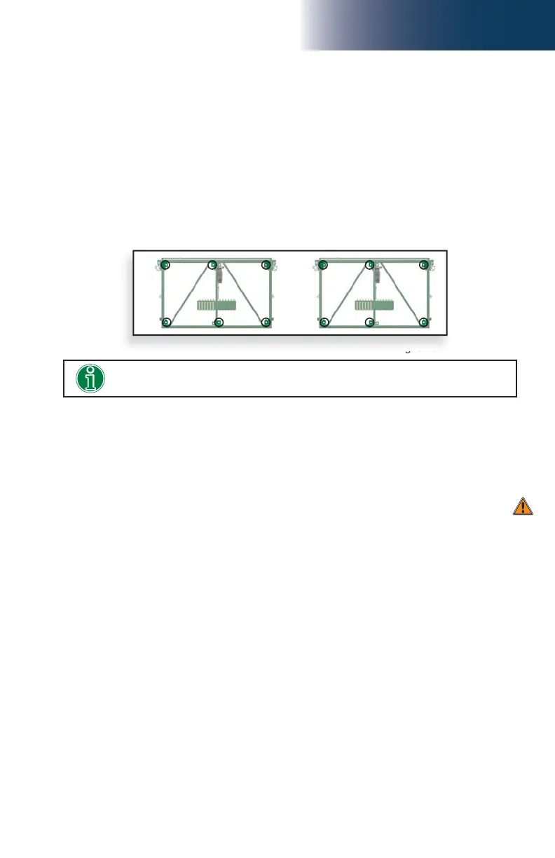
fi g. 3.13
3 - B
Dismantling a bearing bridge structure
1- Make sure the bearing bridge structure is at base level.
2- Make sure that all cantilevers have been removed. Completely unload the working
platform and make workers step off the structure.
3- Disconnect the inclinometers at both ends of the bearing structure and disable the
inclinometer options on each screen.
4- Replace the locking pins, tabs or plates on each twin mast adapters.
5- Using a rough terrain forklift, a crane or any other appropriate lifting device, support
the bearing bridge structure. Unbolt the twin mast adapters from the main frames of
the motorized units.
6- Slightly raise the bearing bridge and lower it on the ground to dismantle it.
Bridges
Bearing Bridge
Installation of the bearing bridge structure
2- Align the twin mast adapter with the bearing bridge structure using the tapered bushings
(see fi g. 3.2).
3- Assemble both structures together using six bolt assemblies: one 5/8” x 5 1/2” (GR8)
hex bolt, one 5/8” (GR8) lock washer and one 5/8” (GR8) nut in each of the four
corner tapered bushings and in one of the pairs of bushings in the middle of the bridge
(using top and bottom bushings on either side – left or right, fi g. 3.13). Tighten all bolt
assemblies to a torque of 120 lb-ft (163 N-m).
4- Repeat steps 1 through 3 to attach the second twin mast adapter at the other end of
the bearing bridge structure. The locking pins, tabs or plates must not be unhooked
or unlocked at this point.
1- Using a rough terrain forklift, a crane or any other appropriate lifting device, lift the
bearing bridge structure and lower it into position, between the two motorized units.
2- Bolt each twin mast adapter to the main frame of a motorized unit. If the welded stoppers
on the bottom bushings of the main frame and the twin mast adapter prevent proper
alignment, the twin mast adapter is not correctly positioned.
Installation of a twin mast adapter (cont’d)
Make sure to unlock the locking pins, tabs or plates on each twin mast adapter.
Failure to do so could result into serious damages.
3- Connect each inclinometer to the control panel. For more information on the installation
and use of the inclinometer, see p. 46 of the Safety Devices section.
4- Enable the inclinometer option on each screen of the bearing bridge installation.
Refer to p. 82 of the Control Panel section for instructions on how to enable the
inclinometer option.
5- Perform the 0-degree level adjustment for each inclinometer. Refer to p. 47 of the
Safety Devices section for instructions on the 0-degree level adjustment procedure.
6- Install a twin mast adapter guardrail on each twin mast adapter and secure in place.
The fi rst bridge bolted to the twin mast adapter must not be a 30" (76 cm) bridge as
the 30" (76 cm) guardrail will interfere with the twin mast adapter guardrail.