127
fi g. 8.84
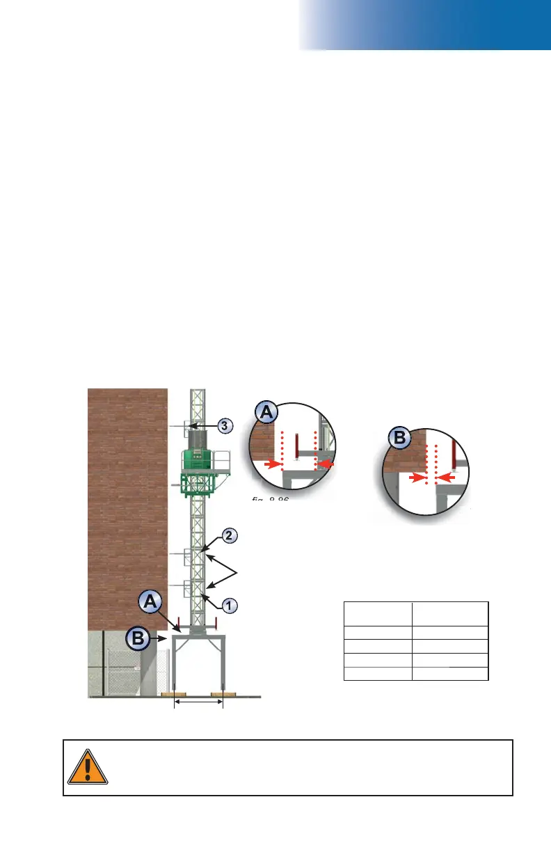
fi g. 8.85
fi g. 8.86
fi g. 8.87
8 - A
Adapter Base for Sidewalk Canopy Installation
(optional)
Installation of the adapter base (cont’d)
3- The bearing surface under the support frames must be level, clear of debris and have
a bearing capacity suffi cient to support the load under each screw jack. It is important
to make sure that the bearing surface is stable and has not been subject to any type of
erosion or deterioration caused by weather conditions (snow, rain, etc.). When required,
appropriate cribbing must be placed under each screw jack on the legs of each support
frame to distribute the load.
4- Typically, for an installation without any planking, the support frames for the adapter
base will be installed at 6" (15 cm) from the face of the wall.
5- Mark the position of jacks. The distance between the front and rear jacks is 91" (2,3 m),
while the distance between the left and right jacks is 74" (1,9 m) (fi g. 8.78, p. 126).
6- Using the supplied cross braces, assemble the two support frames together. Verify the
squareness of the assembly and make corrections, if necessary.
7- Loosen the retaining bolt on each leg of the frames (fi g. 8.76, p. 126) to release the
screw jacks.
8- Using a rough terrain forklift or a crane, lift and position the adapter base on top of
the support frame assembly. Refer to the table in fi g. 8.85 to determine the distance
between the mounting fl ange on the adapter base and the front edge of the support
frame assembly. The adapter base will be moved back by 10" to 12" (25 cm to 30 cm)
from the front edge of the support frame assembly for each plank required by the
confi guration (as shown in fi g. 8.84). If necessary, install the support frame assembly
further back from the face of the wall for larger planking confi gurations (see step 1
and fi g. 8.87). Use the Outrigger Selection table on p. 111 as a guide for planking
confi gurations.
WARNING
Once the unit is installed on the adapter base, it is mandatory to install the fi rst
three tie levels before proceeding with the installation.
Unit on adapter base for sidewalk canopy
installation with two-plank confi guration
Unit must be held up by a crane
or rough terrain forklift during
installation until the fi rst two tie
levels are installed
Number of
planks
Distance “A”
0 15" (38 cm)
1 25" (64 cm)
2 35" (89 cm)
3 45" (114 cm)
Clearance between wall and frame
assembly must be 6" (15 cm)
First tie level on fi rst full
mast section
Second tie level on second
full mast section
91" (231 cm)
Distance “A” in the above table is based
on a 6" (15 cm) clearance between the
support structure and the face of work
(shown as “B”), with a 10" (25 cm) wide
planking confi guration.