121
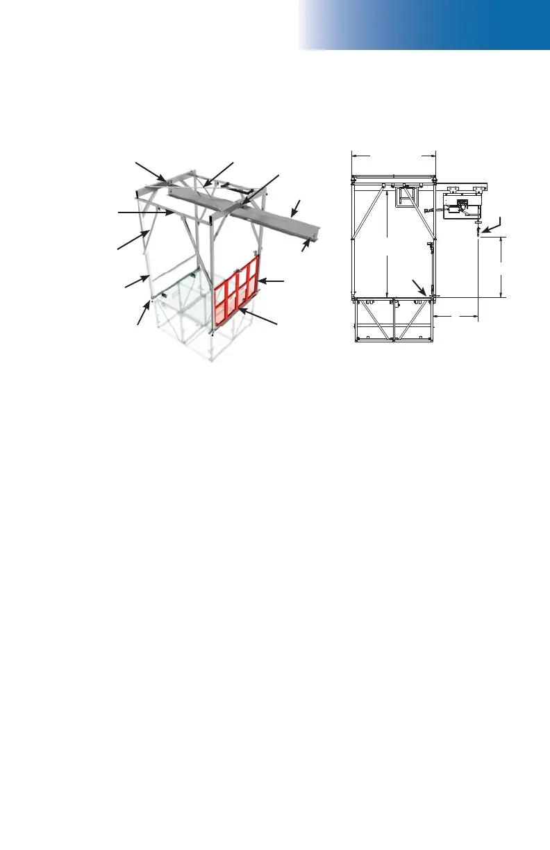
fi g. 8.52 fi g. 8.53
8 - A
Hoist Support Assembly
The optional hoist support assembly can be installed on F2 Series bridges and is designed
to be used with an electric hoist with a maximum lifting capacity of 1000 lb (454 kg) (lifting
capacity based on a hoist weighing 250 lb or 113 kg).
Installation
1- The hoist assembly must be installed on the fi rst bridge closest to the motorized unit.
Refer to p. 104 and p. 105 of the Load Capacities section for more information on
the allowed location and load capacities of a hoist and its support assembly.
2- Insert the back arch support (fi g. 8.52) into the outrigger pockets on the bridge. Do not
tighten the outrigger pocket bolts completely at this point.
3- Insert the front arch support in the outrigger pockets on the bridge. Do not tighten the
outrigger pocket bolts completely at this point.
4- Slide the back side arch assembly onto the threaded rods of the back arch support.
5- Slide the front side arch assembly onto the front arch support. Insert the pivot bolts
into the forks to secure the arch in place. Make sure the locking bolts are in place.
6- Install the two horizontal braces on top of the mounting pins to link the front and back
arches together. Secure the braces to the arches with hitch pins.
7- Install the four diagonal braces to make the assembly more rigid. Secure the braces
to the horizontal braces and to the arches with hitch pins.
8- Slide the I beam in the assembly and secure to the front and back arches with bolt
assemblies.
9- Install the cross brace over the mounting pins on top of the assembly. Secure to the
front and back arches with hitch pins.
10- Make sure the assembly is plumb on all its axis, front and back. Tighten all bolt assemblies
properly.
11- Remove the stop pin and install the electrical hoist (not supplied) as per the manufacturer’s
instructions. Replace the stop pin.
(optional)
Cross brace
“I” beam
Stop pin
Diagonal
brace
Horizontal
brace
Front (wall
side) arch
assembly
Back (door
side) arch
assembly
Front arch
support
Back arch
support
Beam support
Beam support
67" (170,2 cm)
85" (215,9 cm)
clearance
36" (91,4 cm)
maximum
cantilever
distance
48"
(122 cm)
maximum
distance
between
top of
deck and
hook
Hook
Top of
deck