82
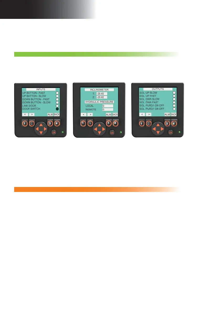
fi g. 5.14 fi g. 5.15 fi g. 5.16
5 - C P
Screen alerts and instructions
Control Panel
F3 – Inputs and outputs
This section displays information about the various controls, sensors and switches linked
to the input and output ports of the control panel. A black circle will indicate that the control
panel receives a signal from a sensor or sends a signal to an actuator. Other information
will be displayed in values. These pages are mainly useful for troubleshooting operations to
provide information on the condition of the unit and the setup to a remote qualifi ed technician.
Access level: Operator
1- Press the F3 button on the main menu page (button 3 in fi g. 5.6, p. 76).
2- Change display pages with the option buttons (buttons 1 and 2 in fi g. 5.14).
3- Press the
BACK button (button 4 in fi g. 5.14) to return to the main menu page.
Note: Numbers on the above option buttons are displayed as an example only. Actual messages displayed may diff er
from picture.
1
2
3
4
1
2
3
4
1
2
3
4
Access level: Erector / Dismantler
Access level: Erector / Dismantler
F4 – Confi guration
1- Press the
F4 button on the main menu page (button 4 in fi g. 5.6, p. 76).
2- On the access code entry page, press on the
OK button. Once the input box is blinking,
use the UP and DOWN arrows (on the navigation button) to change the value (access
code available only to the qualifi ed erector/dismantler), then press OK to access the
confi guration options section pages.
3- Change display pages with the option buttons (buttons 1 and 2 in fi g. 5.14).
4- Use the
UP and DOWN arrows on the navigation button to reach the box to be modifi ed.
5- Press the
OK button to select the box to be modifi ed.
6- Once the selected box is blinking, use the
UP and DOWN arrows on the navigation
button to change the value displayed in the box.
7- Press the
OK button to confi rm the change.
8- Press the
BACK button (button 4 in fi g. 5.14) to return to the main menu page. Access
to the confi guration options section will automatically be deactivated once the user
leaves the section. The access code to access this level will need to be entered again.
This fi ve-page section includes: one access code entry page for this section (accessible
only to the qualifi ed erector/dismantler) and three pages for the modifi cation of setup
confi guration options, including enabling the inclinometer. The last page of the section is
an access code entry page giving access to options available only to a qualifi ed technician.