100
700 lb
318 kg
700 lb
318 kg
2750 lb
1247 kg
15' (4,6 m)
Total 1400 lb
635 kg
10' (3 m)
Total 2750 lb
1247 kg
150 lb
68 kg
Total 450 lb
204 kg
150 lb
68 kg
150 lb
68 kg
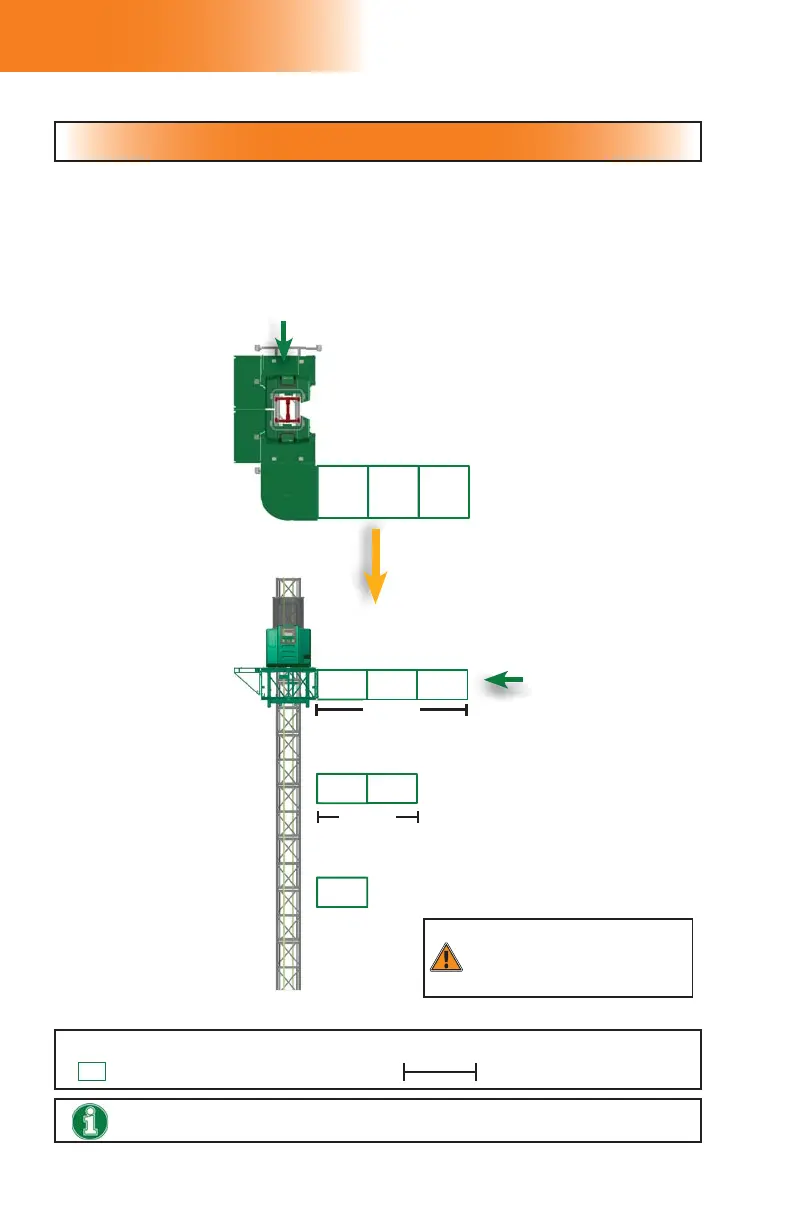
fi g. 6.12
fi g. 6.13
7 - L C
Load Capacities
Swivel bridge installation – Single unit (90 degrees)
Swivel bridge installation – Single unit (90 degrees)
(linked or unlinked)
View from
top
Side view
To ensure safety at all times, refer to load calculation guidelines and warnings on p. 94.
LEGEND
5' (1,5 m) bridge assembly Length of bridge setup
At this end, it is mandatory to install a bridge.
The only bridge confi gurations allowed at this end are the following:
Any cantilever confi guration (see p. 95 for a linked cantilever or p. 97 for an unlinked cantilever)
— OR —
any bearing bridge confi guration (see p. 96 for a linked confi guration or p. 98 for an unlinked
confi guration
— OR —
any swivel bridge confi guration shown in this chart.
NO CONFIGURATION OTHER THAN THOSE ABOVE ALLOWED AT THIS END
Total of 450 lb (204 kg) evenly
distributed on three bridges
OR
300 lb (136 kg) on one of the
three bridges
WARNING
The use of weather protection is
NOT ALLOWED for swivel bridge
installations.