16
1
2
1
2
2
fi g. 1.21
fi g. 1.24
fi g. 1.22
fi g. 1.23
1 - M U
Positioning the Motorized Unit
Bearing surface
Before installing the motorized unit, make sure the bearing surface under it is level, clear of debris
and has the proper bearing capacity. Appropriate cribbing must be placed under the base to
distribute the load. It is important to make sure that the bearing surface is stable and has not been
subject to any type of erosion or deterioration caused by weather conditions (snow, rain, etc.).
General Concept
Recommended cribbing for most bearing surfaces
The plywood and lumber used as cribbing must be secured together to prevent slipping. Using
screws instead of nails for securing will prolong the service life of lumber and plywood used
as cribbing.
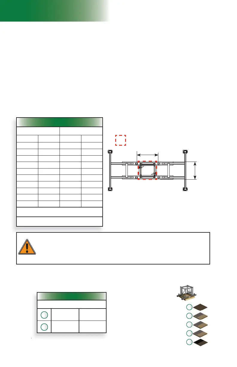
Values shown in the above table are for reference only. Any cribbing that
covers the mandatory cribbing area (as shown in fi g. 1.22) can be used.
The type of cribbing chosen may vary according to the bearing surface where the setup
must be installed.
For example, a setup installed on a concrete slab that is covering the bearing surface would
require cribbing consisting of only one plywood panel under the base while a setup installed on
a concrete slab that is covering an indoor garage would require shoring in addition to plywood
cribbing.
A setup installed on a bearing surface composed of gravel, sand or any such type of surface
would require stronger cribbing under the base.
In cases where shoring is required, it is recommended to contact an engineer for assistance.
WARNING
Make sure the ground or support surface capacity meets with values included in the
Minimum Bearing Surface Capacities table (fi g. 1.21). Soil compacting, cribbing or shoring
can increase bearing capacity. Any cribbing product or cribbing method approved by the site
engineer can be used to distribute the load on the bearing surface providing it meets the
values in the Minimum Bearing Surface Capacities table (fi g. 1.21). Contact an engineer for
assistance.
Minimum Bearing Surface Capacities
Minimum Bearing Surface Capacities
Height Reaction
ft m lb kg
50 15 28 816 13 071
100 30 32 559 14 769
150 46 36 302 16 466
200 61 40 045 18 164
250 76 43 788 19 862
300 91 47 531 21 560
350 107 51 272 23 257
400 122 55 017 24 955
450 137 58 760 26 653
500 152 62 503 28 351
Note: Reactions shown in this table are for tied
installations only
Load reactions in table above include a dynamic
factor
hown in the above table are
or re
erenc
Recommended Cribbing
40" x 40" x 6"
(102 cm x 102 cm x
15,2 cm)
Plywood
40" x 40" x 3/4"
(102 cm x 102 cm x 1,9 cm)
2
Lumber
2"x 10" x 40"
(5 cm x 25 cm x 102 cm)
12
1
2
Plywood
3/4" (1,9 cm)
Lumber
1 1/2" (3,8 cm)
Plywood
3/4" (1,9 cm)
Lumber
1 1/2" (3,8 cm)
Lumber
1 1/2" (3,8 cm)
32" (81,3 cm)
32"
(81,3 cm)
Mandatory cribbing area