21
fi g. 1.31
1 - M U
Setup and confi gurations
10- With the motorized unit to base level and using bridge installation support brackets or
any other appropriate lifting device such as a crane or a rough terrain forklift, install as
many bridges as is required and allowed. It is important to note that bridge installation
support brackets cannot be used when installing the fi rst bridge attached to the
motorized unit (see p. 110 for more information). For instructions on how to install a
bridge, refer to p. 50 of the Bridges section. Refer to the Load Capacities section
on p. 94 for the maximum number of bridges allowed in a setup.
Installation of bridges
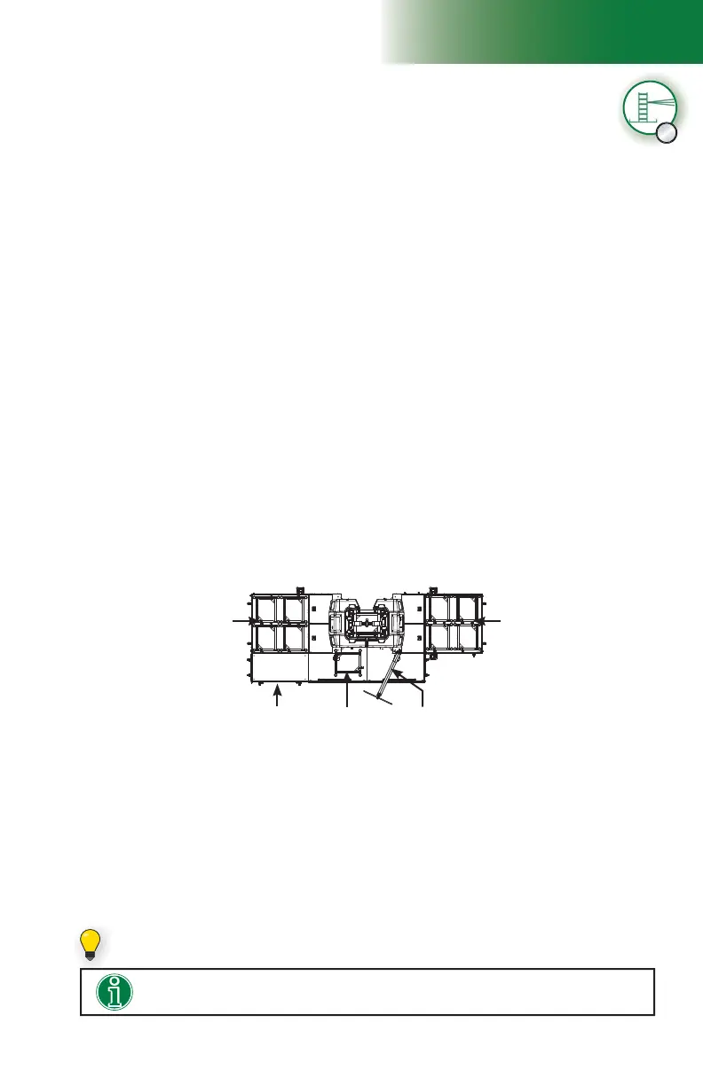
11- Using an optional jib arm, a crane or a rough terrain forklift, load mast sections on
the motorized unit (see p. 119 of the Accessories section for more information on
the installation and use of a jib arm). There can be up to a maximum of four mast
sections on each side of the mast at a time.
A ninth mast section can be loaded on the link bridge of the motorized unit, as shown
in fi g. 1.31. It is recommended to install an optional deck extension on one of the fi rst
cantilevers attached to the unit to facilitate the handling of mast sections with the jib
arm. The deck extension must be installed on the side opposite to the jib arm, as
shown in fi g. 1.31. For information about the use and installation of an optional deck
extension, refer to p. 55 of the Bridges section.
Installation of mast sections and tie levels
Standard single unit installation with mast ties – progressive installation
A
Verifi cation of limit switches and screen alerts (cont’d)
7- Inspect the strobe under the main frame and make sure it is working properly.
8- Review the screen alerts and perform a verifi cation of the limit switches. For instructions
on how to verify the limit switches, refer to p. 48 of the Safety Devices section.
9- If any of the limit switches is not working properly, the unit must be put out of service
until it has been inspected and repaired by a qualifi ed person. For the defi nition of a
qualifi ed person, refer to p. 7 of the Performance and Safety section. For more
information about limit switches and their corresponding alerts, refer to p. 77 of the
Control Panel section.
Mast sections must be loaded equally on either side of the mast and taken alternately
from one side, then the other when installing to ensure good balance. Refer to the
Load Capacities section on p. 94 for more information about loading the platform.
12- Install mast sections until a fi rst tie level is required. For instructions on how to install
mast sections, refer to p. 84 of the Mast and Mast Ties section. Refer to p. 86 of
the Mast and Mast Ties section for instructions on how to install mast ties. For more
information about the schedule of installation of tie levels, refer to the Mast Tie Schedule
tables on p. 87 of the Mast and Mast Ties section.
Optional deck
extension
Mast section
loaded on the
link bridge
Jib arm
Four mast sections
on fi rst cantilever
attached to unit
Four mast sections
on fi rst cantilever
attached to unit
It is important to note that at least two tie levels must be in place before any work
can be performed from the platform.
Installing an optional deck extension will facilitate the handling of mast sections
with the jib arm.
If it is required to load 45' (13,7 m) of mast sections, a ninth mast section can be set
on the link bridge of the motorized unit.