28
fi g. 1.35
fi g. 1.36
fi g. 1.37
1 - M U
Setup and Confi gurations
Multiple units installation with mast ties – pre-installation
(requires two twin mast adapters – sold separately)
16- Upon initial setup and subsequently after every 8 to 10 hours of cumulative runtime (unit
travel up and down the mast), grease must be applied to the gears and to the racks, from
the top of the mast down. For more information, refer to the daily inspection checklist for
this motorized unit. Grease must be allowed to stand for 2-3 hours before the motorized
unit is used again. Use an open gear lubricant recommended by Hydro Mobile. Refer
to p. 133 of the Transport, Storage and Maintenance section for more information on
the appropriate lubrication method. Lower the motorized unit to base level, verifying
the mast ties and the mast bolts and applying grease, as required, on the way down.
Make sure that all bolt assemblies are tightened to the proper torque and are in good
condition, and that grease is applied appropriately.
Greasing of the racks and gears
17- Once grease has been applied to the gears and the mast racks, install all mast guards.
Remove and store the jib arm, if necessary.
Installation of the mast guards
2
Installation of the second motorized unit
Positioning and installing the second motorized unit
1- Determine the position of the second motorized unit according to the length of the
bearing bridge to be installed.
2- To determine the length of the bearing bridge, use the Distances for a bearing
installation table in fi g. 1.35 as a guide or assemble the bearing bridge and measure the
overall length of the structure, including the twin mast adapters at each end of the structure.
If required, refer to the safety guidelines and to steps 1 through 4 of the instructions for
the assembly of a bearing bridge structure on p. 52 of the Bridges section.
3- Install the second motorized unit following steps 1 through 18 of the installation
instructions for the fi rst motorized unit, starting on p. 26.
Distances for a bearing installation
Distances for a bearing installation
(approximate distances)
No. of bridges
Distances from
center to center of masts
Distances between main frames
10 65' (19,8 m) 55' (16,8 m)
9 60' (18,3 m) 50' (15,2 m)
8 55' (16,8 m) 45' (13,7 m)
7 50' (15,2 m) 40' (12,2 m)
6 45' (13,7 m) 35' (10,7 m)
5 40' (12,2 m) 30' (9,1 m)
4 35' (10,7 m) 25' (7,6 m)
3 30' (9,2 m) 20' (6,1 m)
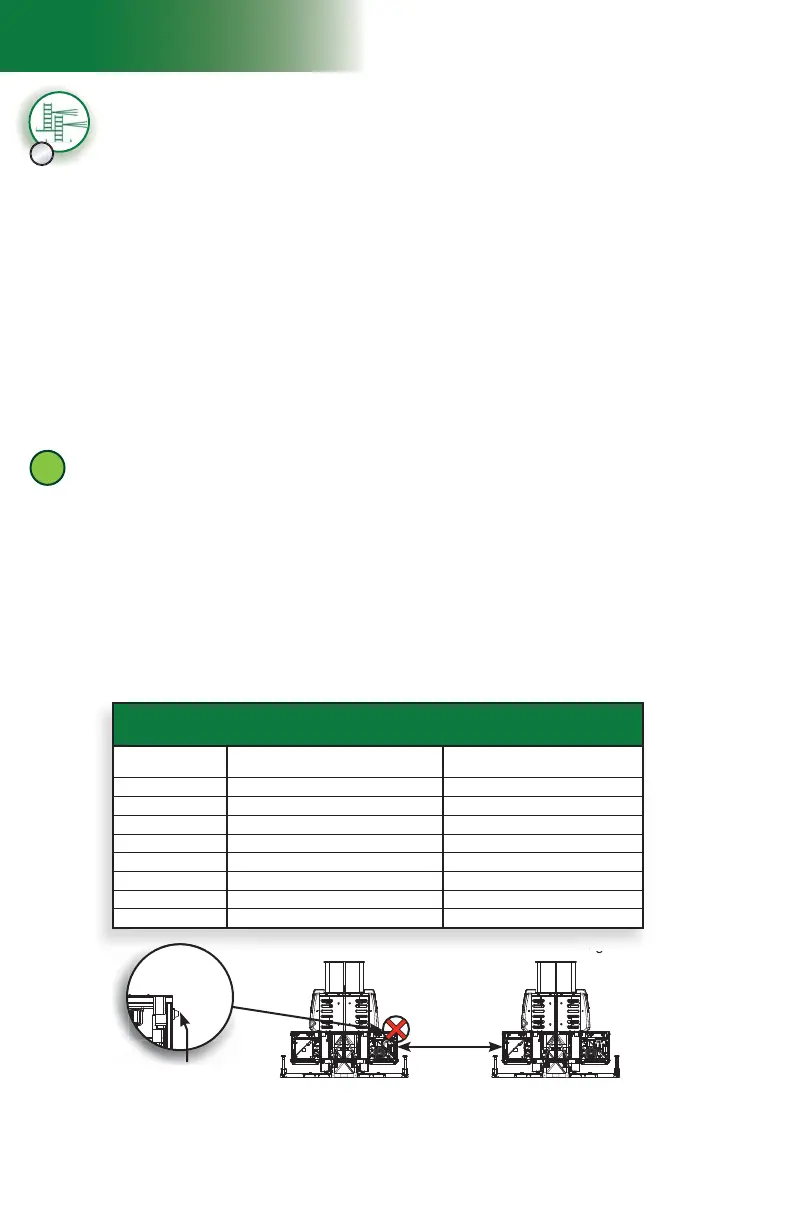
C
It’s important to make sure that the distance between the two motorized units is measured from
frame to frame and not from bushing to bushing (fi g. 1.37).
Distance
measured from
frame to frame
Bushing on main
frame of unit