32
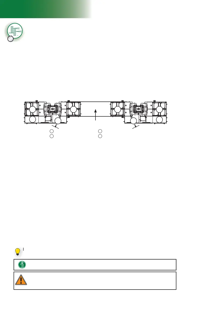
fi g. 1.39
A
C
DD
BBA
C
1 - M U
Setup and Confi gurations
Multiple units installation with mast ties – pre-installation
(requires two twin mast adapters – sold separately)
WARNING
During pre-installation, only mast sections can be loaded on the cantilevers and on the fi rst
bridge at each end of the bearing bridge structure. It is important to note that no other loads are
allowed on the bridges until the pre-installation process is complete.
20- Using an optional jib arm, a crane or a rough terrain forklift, load mast sections on
each motorized unit (see p. 119 of the Accessories section for more information on
the installation and use of a jib arm). There can be up to a maximum of four mast
sections on each side of the mast at a time.
A ninth mast section can be loaded on the link bridge of each motorized unit, as shown
in fi g. 1.39. It is recommended to install an optional deck extension on the fi rst cantilever
attached to each unit to facilitate the handling of mast sections with the jib arm. The
deck extension must be installed on the side opposite to the jib arm, as shown in
fi g. 1.39. For information about the use and installation of an optional deck extension,
refer to p. 55 of the Bridges section.
Installing and testing the top limit switches
24- Make sure that the top limit trigger plate on the mast head is in a vertical position on
each motorized unit. If necessary, loosen the thumb screws, fl ip the trigger vertically
and tighten the thumb screws by hand.
25- Test the operation of the top limit switches by raising the motorized units until the
switches reach the trigger plates. Each screen should display an alert for the top limit.
If any of the limit switches is not working properly, call the distributor/service center. For
more information about limit switches and their corresponding alerts, refer to p. 77
of the Control Panel section.
Mast sections must be loaded equally on either side of each mast and taken alternately
from one side, then the other when installing to ensure good balance. Refer to the
Load Capacities section on p. 94 for more information about loading the platform.
21- Install mast sections until a fi rst tie level is required. For instructions on the installation of
a mast section, refer to p. 84 of the Mast and Mast Ties section. Refer to p. 86 of
the Mast and Mast Ties section for instructions on how to install mast ties. For more
information about the schedule of installation of tie levels, refer to the Mast Tie Schedule
tables on p. 87 of the Mast and Mast Ties section.
22- Once the fi rst tie level has been installed on both motorized units, proceed with the
installation of as many mast sections and tie levels on each motorized unit as is
required by the layout plan and the confi guration. Any F2 Series motorized unit must
not be used on a mast with a height over 500' (152 m).
23- Install the mast head on top of the last mast section on each motorized unit.
Installation of the mast heads
D
Installation of mast sections and tie levels
A
Four mast sections on fi rst cantilever attached
to unit
C
Optional deck extension installed on the opposite
side of the jib arm
B
Four mast sections on fi rst bridge of the bearing
bridge structure
D
Jib arm installed on the opposite side of the
deck extension
Bearing bridge structure
Installing an optional deck extension will facilitate the handling of mast sections
with the jib arm.
If it is required to load 45' (13,7 m) of mast sections, a ninth mast section can be set
on the link bridge of the motorized unit.