35
A
A
A
B
B
B
fi g. 1.45
fi g. 1.46
fi g. 1.48
fi g. 1.47
fi g. 1.49
fi g. 1.50
fi g. 1.44
g. 1.5
1 - M U
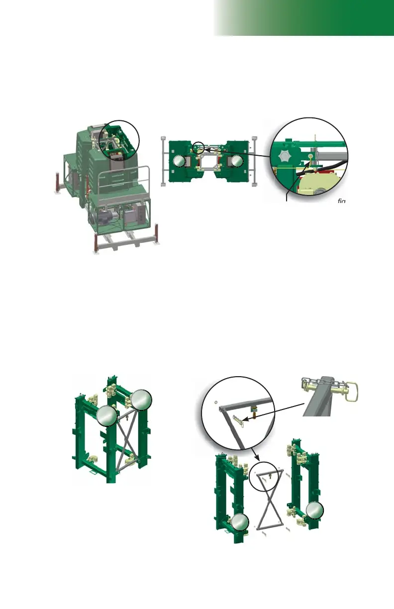
Splitting a motorized unit (applicable to model F300 only)
Location of the trolley link
sensor
Cable connected to
trolley link sensor
(yellow in image)
Hitch pin
assembly
Trolley link
Setup and Confi gurations
Removal of the trolley link (cont’d)
9- On one side of the motorized unit only (shown as “A” in fi g. 1.45 for illustration
purposes only), disconnect the cable connected to the trolley link sensor located at
the top of the main trolley.
10- Remove the hitch pin assemblies on that side only (shown as “A” in fi g. 1.45.
11- Carefully raise that side of the unit to have enough clearance to remove the trolley link
(about 6" to 12" or 15 cm to 30 cm).
12- Support the trolley link and remove the remaining hitch pin assemblies. Remove the
trolley link and store it properly.
13- Reconnect the trolley link proximity switch disconnected in step 9.
14- On the display screen, scroll to the inputs page and make sure that the
LINK DOOR is
detected but not the trolley link.
15- Proceed in reverse order to relink both sides of the motorized unit.