62
2
3
4
7
6
10
9
S
fi g. 3.47
11
12
fi g. 3.48
13
3 - B
Bridges
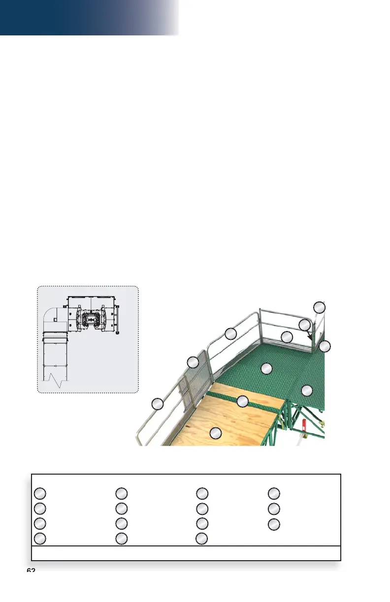
Swivel Bridge Guardrails
Bearing Bridge Confi gurations
Front bearing confi guration – 90° angle
1- Make sure that the adjustment rod is installed on the appropriate side of the bridge to
achieve the desired confi guration. If required, remove the bolt assemblies at both ends
of the adjustment rod and reinstall it on the other side of the bridge (fi g. 3.26, p. 56).
2- Part “A” of the swivel bridge guardrail assembly is not required for 90° front bearing
confi gurations. Separate all three parts (“A”, “B” and “C”) of the swivel bridge guardrail
assembly, if necessary.
3- Align the plates of the guardrail adapter (fi g. 3.43, p. 60) with the side of the 27" (69 cm)
guardrail on the link bridge of the unit and secure in place with bolts.
4- Install part “B” of the swivel bridge guardrail assembly backwards (as shown in fi g. 3.47)
and align its hinge tubes with the hinge tubes on the adapter on the 27" (69 cm) guardrail
on the link bridge of the unit. Secure in place with guardrail pins (fi g. 3.43, p. 60)
5- Insert the guardrail assembly pins on part “C” in the corresponding hinge tubes on part
“B”. Secure the assembly with cotter rings.
6- Install the twin mast adapter guardrail on the twin mast adapter.
7- Secure part “C” of the swivel bridge guardrail assembly to the twin mast adapter guardrail.
8- Make sure all the necessary guardrails are in place and secure (see the Accessories
section on p. 108 for more information about guardrails). In all cases where workers
are exposed to fall hazards greater than specifi ed by local regulations, the installation
of guardrails or face guardrail supports is mandatory.
Front 90° bearing confi guration
90°
LEGEND
Part “A” of swivel bridge
guardrail assembly
Sliding bracket to secure
guardrails together
5' (1,5 m) bridge
Standard 27" (69 cm)
guardrail
Part “B” of swivel bridge
guardrail assembly
Standard 60" (1,5 m)
guardrail
Twin mast adapter Link bridge guardrail
Part “C” of swivel bridge
guardrail assembly
Twin mast adapter
guardrail
Motorized unit Swivel bridge
Guardrail adapter Gap fi ller Link bridge
Note: Not all components are required for each confi guration
1
2
3
4
5
6
7
8
9
10
11
12
13
14
S