EasyManuals Logo
Home>Hypertherm>Welding System>XPR170

Hypertherm XPR170 Replacement Part Procedures

Hypertherm XPR170
176 pages
To Next Page IconTo Next Page
To Previous Page IconTo Previous Page
Page #112 background imageLoading...
Page #112 background image
Torch Connect Console
3
11 2 810410 Field Service Bulletin XPR170
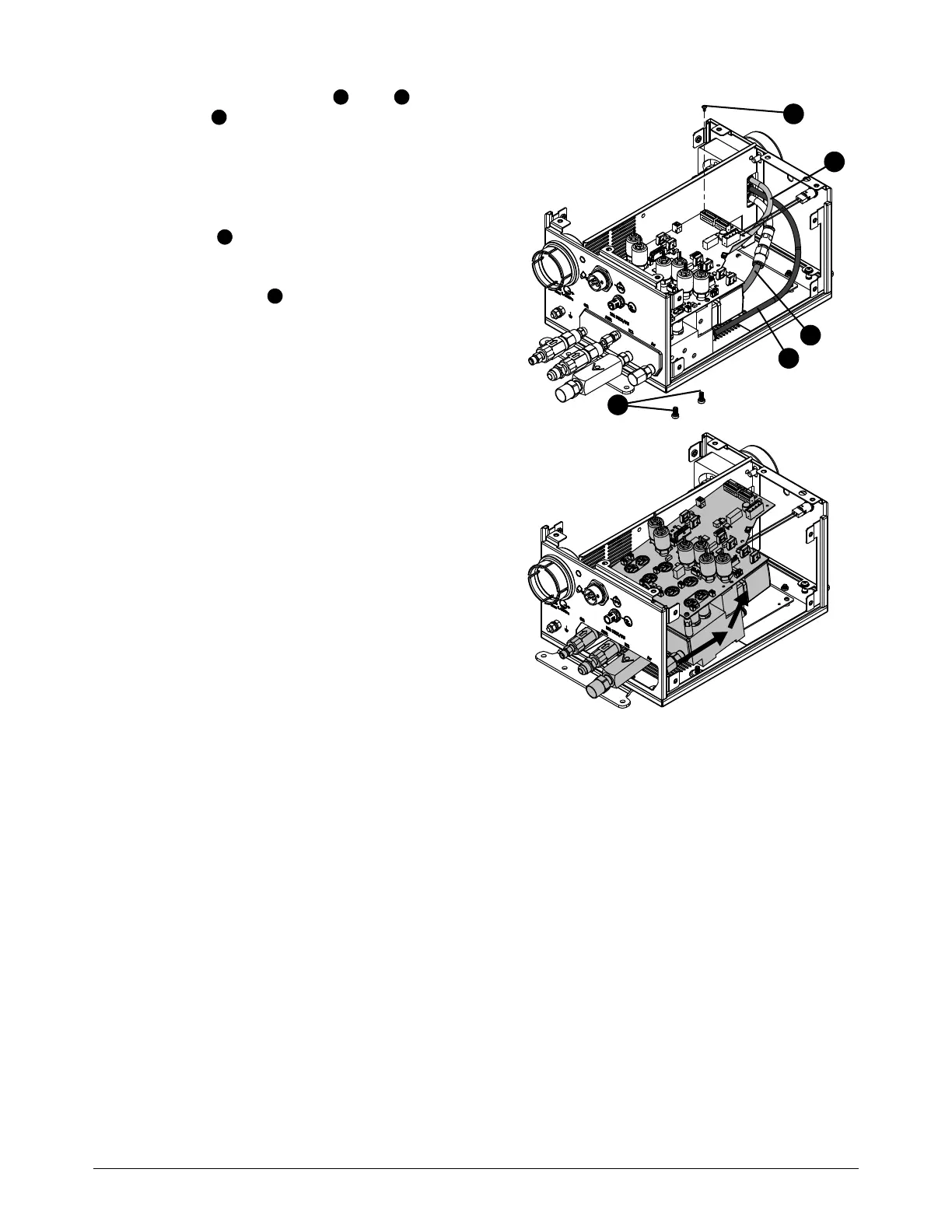
6. Disconnect the yellow , blue , and
black tubes from the push-to-connect
fittings on the manifold assembly. Refer to
How to use push-to-connect fittings on
page 102.
7. Use a Phillips screwdriver to remove the
screw from the control PCB.
8. Use a 3 mm, hexagonal-key wrench to remove
the 2 screws that hold the manifold
assembly in the bottom of the torch connect
console.
9. Slide the manifold assembly with control PCB
back and lift out.
2
3
4
6
5
2
3
4
5
6

Table of Contents

Other manuals for Hypertherm XPR170

Questions and Answers:

Question and Answer IconNeed help?

Do you have a question about the Hypertherm XPR170 and is the answer not in the manual?

Hypertherm XPR170 Specifications

General IconGeneral
BrandHypertherm
ModelXPR170
CategoryWelding System
LanguageEnglish

Related product manuals