Gas Connect Consoles
78 810410 Field Service Bulletin XPR170
Replace the 24 V power source
Refer to Core, VWI, and OptiMix gas connect console manifold side on
page 143 for location and part number.
1. Complete the following procedures:
a. Remove the power from the cutting system.
b. Remove the top panel
c. Remove the manifold-side panel.
Refer to Gas connect console panels on page 100.
Keep all nuts and screws that you remove.
2. Remove all of the wires.
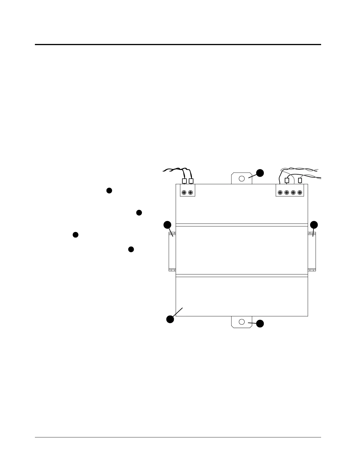
3. Use a blade screwdriver to pull out
the plastic tabs on the power
source.
4. Remove the power source .
5. Align the new power source on the
rail .
6. Push in the plastic tabs to
attach the power source to the rail.
7. Install the wires L, N, +, -. Tighten
the screws.
8. Install the unlabeled wires.
Connect the red wire to + and
white wire to -. Tighten the screws.
9. Install the control-side panel.
 Loading...


