Plasma Power Supply
XPR170 Field Service Bulletin 810410 15
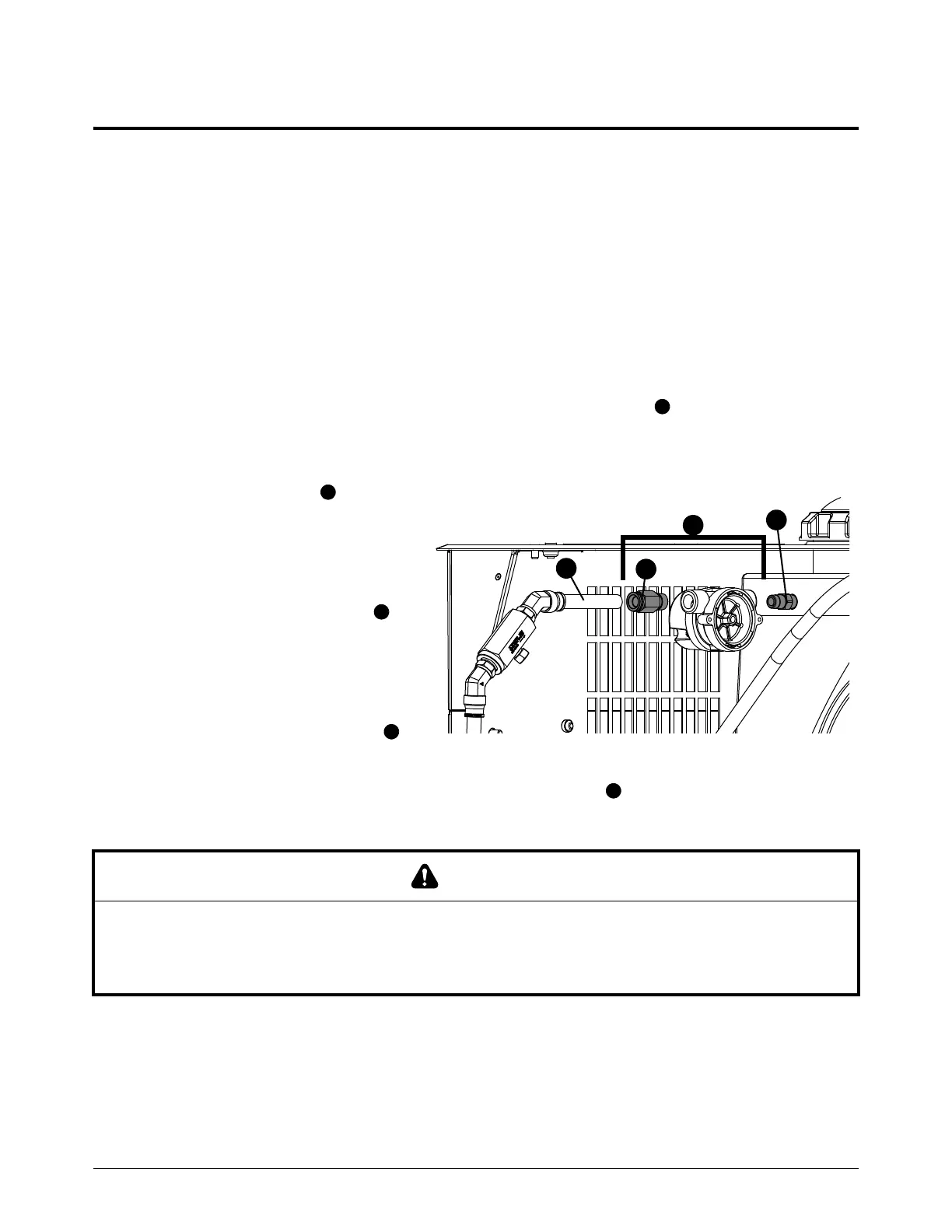
Right-side (liquid-cooling-side) parts
Replace the flow meter
Refer to Coolant system on page 134 for location and part number.
1. Complete the following procedures:
a. Remove the power from the cutting system.
b. Refer to Remove the right-side (liquid-cooling-side) panel on page 62.
c. To make removing the flow meter easier, you can remove the top panel. Refer to Remove the
top panel on page 65.
d. Drain the coolant until the level is below the coolant tank fitting .
Keep all nuts and screws that you remove.
2. Disconnect the tube from the
push-to-connect fitting in the
flow meter. Refer to How to use
push-to-connect fittings on
page 12.
3. Hold the coolant tank fitting
with a 9/16-inch, open-ended
wrench.
4. Turn the flow meter
counter-clockwise to remove the
flow meter and outside fitting
from the coolant tank fitting.
5. Use a 13/16-inch, open-ended wrench to remove the fitting from the flow meter.
6. Apply liquid thread sealant to the fitting threads.
NOTICE
PTFE TAPE CAN CAUSE CLOGGED VALVES, REGULATORS, AND TORCHES
Never use PTFE tape on any joint preparation. Use only a liquid or paste thread sealant on male thread
ends.