Torch Connect Console
XPR170 Field Service Bulletin 810410 11 5
Replace the control PCB
Refer to Torch connect console manifold side – view 1 on page 153 for
location and part number.
Remove the control PCB
1. Complete the following procedures:
a. Remove the power from the cutting system.
b. Remove the gas pressure from the cutting system.
c. Remove the top panel.
d. Remove the control-side panel.
Refer to Torch connect console top panel and side panels on page 126.
Keep all nuts and screws that you remove.
2. Disconnect and remove the pressure transducers. Refer to Replace a pressure transducer on
page 107.
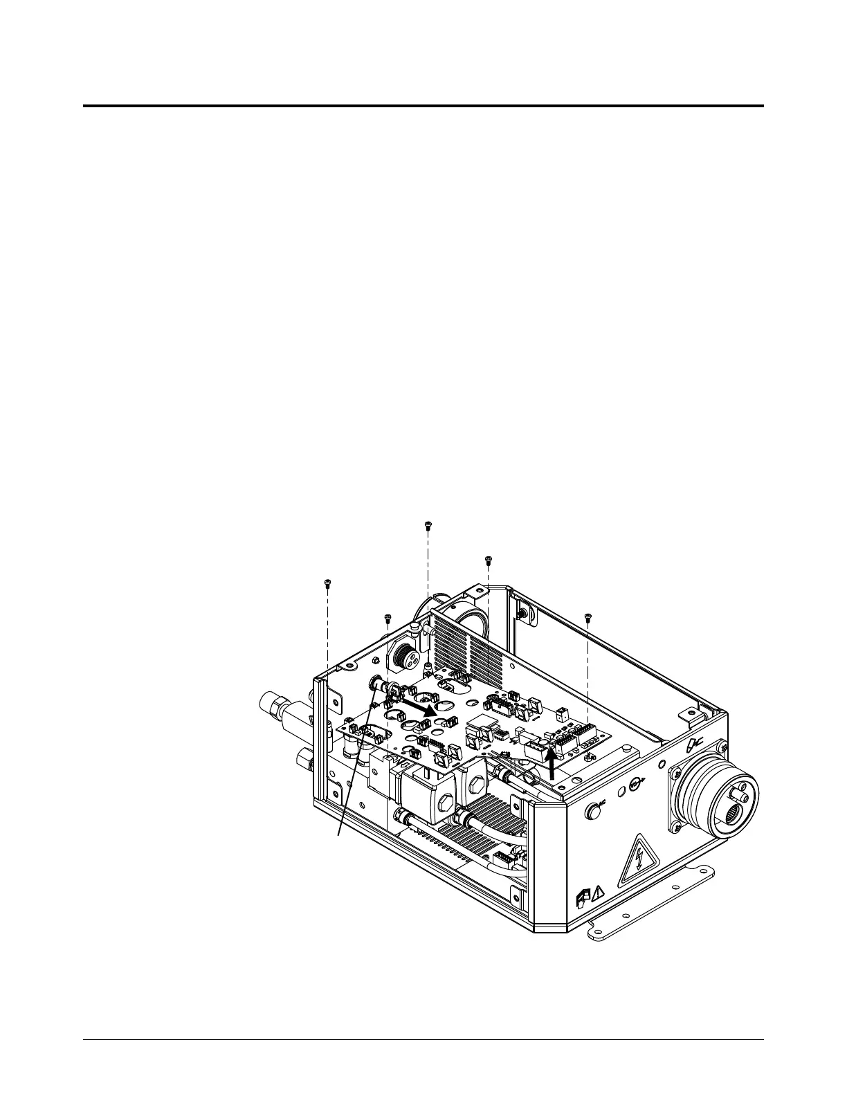
3. Disconnect all
of the wires
from the PCB.
4. Remove the 5
screws from
the PCB.
5. Tilt the end of
the PCB up
and pull the
PCB out.
 Loading...


