Plasma Power Supply
32 810410 Field Service Bulletin XPR170
Left-side (control-side) parts
Replace the chopper
Refer to Control side – view 2 on page 139 for locations and part
numbers.
Remove the chopper
1. Complete the following procedures:
a. Remove the power from the cutting system.
b. Refer to Remove the right-side (liquid-cooling-side) panel on page 62.
c. Refer to Remove the left-side (control-side) panel on page 63.
d. Drain the coolant. Refer to Remove old coolant from the coolant system in the Maintenance
section in the XPR170 Instruction Manual (810060).
Keep all nuts and screws that you remove.
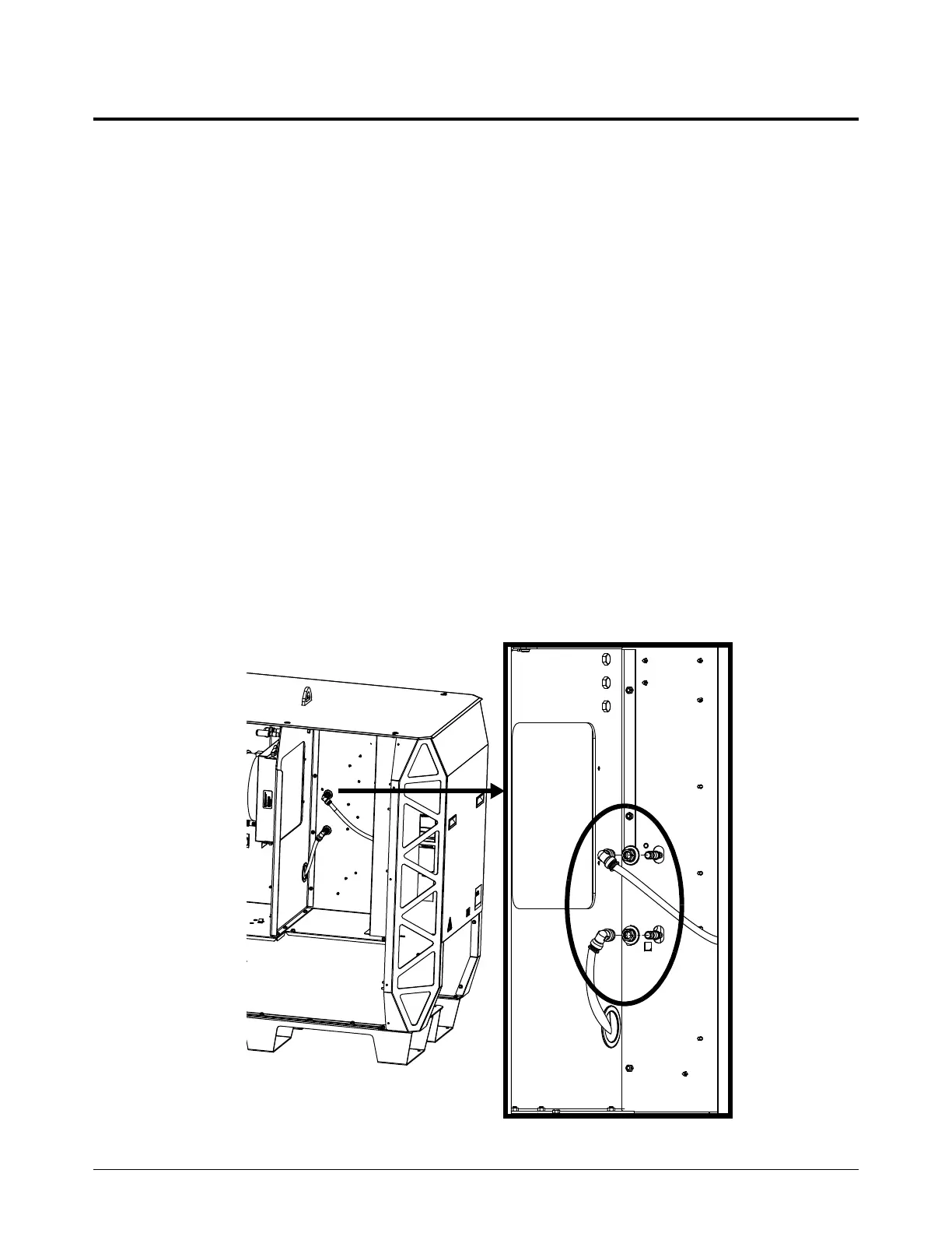
2. Use tape to attach protective material, such as cardboard, onto the rear of the heat-exchanger
assembly to protect the cooling fins.
3. Remove the push-to-connect fittings and retaining nuts from the rear of the chopper that you
want to replace. Refer to How to use push-to-connect fittings on page 12.