Plasma Power Supply
XPR170 Field Service Bulletin 810410 19
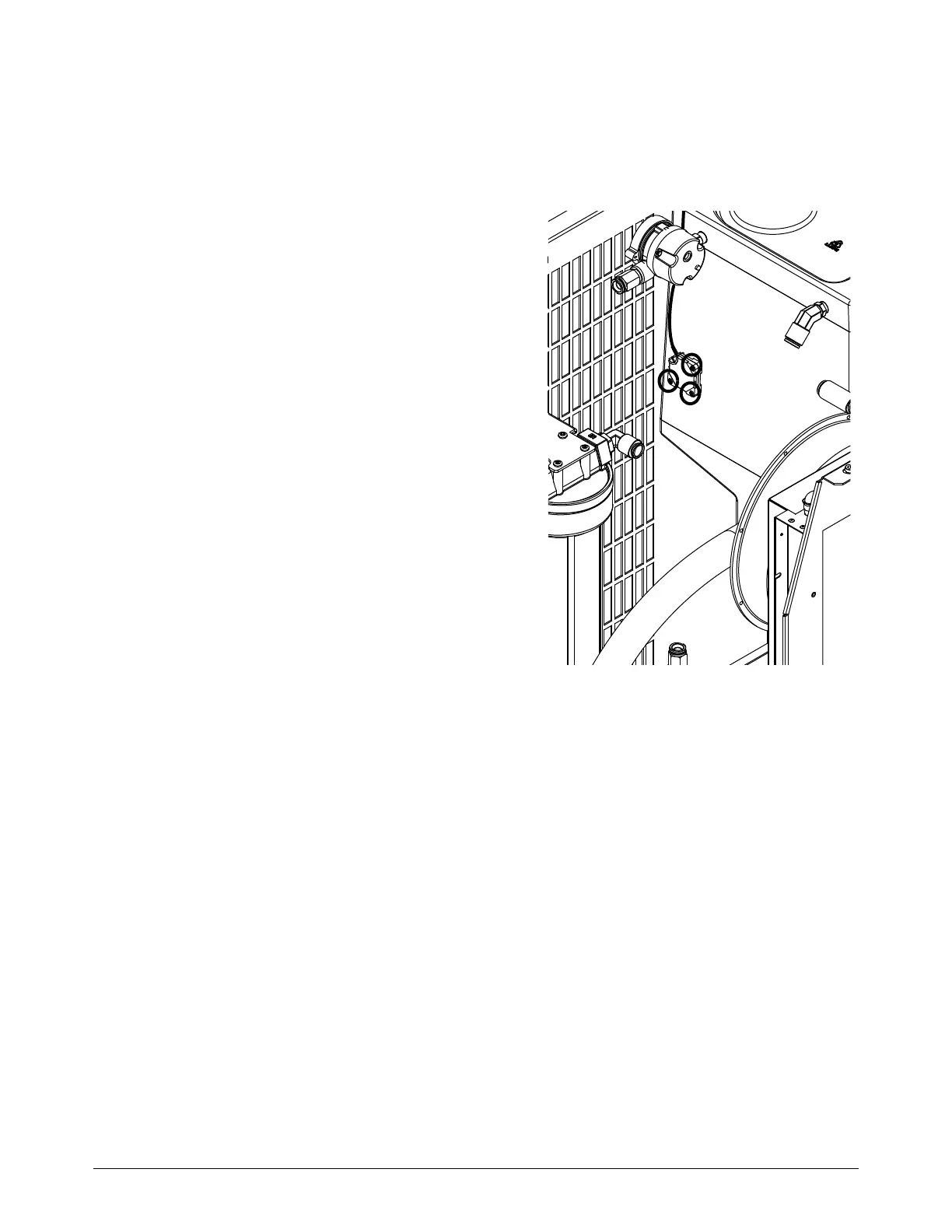
Replace the coolant level sensor
Refer to Coolant system on page 134 for location and part number.
1. Complete the following procedures:
a. Remove the power from the cutting system.
b. Refer to Remove the right-side
(liquid-cooling-side) panel on page 62.
c. Refer to Remove the left-side (control-side)
panel on page 63.
Keep all nuts and screws that you remove.
2. Use a 3 mm, hexagonal-key wrench to remove the
3 screws.
3. Remove J5 from the control PCB.
4. Remove the wire from the wire clips.
Note where the wire is routed.
5. Use the 3 screws to install the coolant level
sensor. Tighten to 6.9 kg∙cm (6 in∙lbf).
6. Route the wire in the same path that you removed
the wire.
7. Connect J1.5 to J5 on the control PCB.
8. Install all of the panels.
9. Use the XPR web interface to make sure that the coolant sensor operates correctly.
For more information on the XPR web interface, refer to the Connect for
Communication in the XPR170 Instruction Manual (810060).