Plasma Power Supply
28 810410 Field Service Bulletin XPR170
Replace the fan power distribution PCB
Refer to Fans on page 133 for location and part number.
1. Complete the following procedures:
a. Remove the power from the cutting system.
b. Refer to Remove the right-side (liquid-cooling-side) panel on page 62.
Keep all nuts and screws that you remove.
2. Disconnect all of the wire connectors.
3. Remove 2 screws from the bottom of the PCB.
4. Pull the PCB off of the 2 push connectors.
5. Align the new PCB with the studs and push it in until you
hear a click.
6. Install the 2 screws.
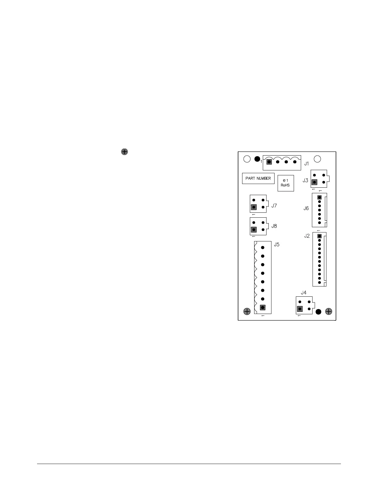
7. Connect the wires:
J1 for the 48 V power source
J2 for the control PCB
J3 for the top heat-exchanger fan
J5 for the magnetics fan
J6 for the control PCB
J7 for the top control-side fan
J8 for the bottom control-side fan
8. Install the right-side (liquid-cooling-side) panel.