Plasma Power Supply
XPR170 Field Service Bulletin 810410 59
Replace the inrush resistor assembly
Refer to Rear compartment of the plasma power supply on page 140 for
location and part number.
1. Complete the following procedures:
a. Remove the power from the cutting system.
b. Refer to Remove the right-side (liquid-cooling-side) panel on page 62.
c. Refer to Remove the rear panel on page 64.
Keep all nuts and screws that you remove.
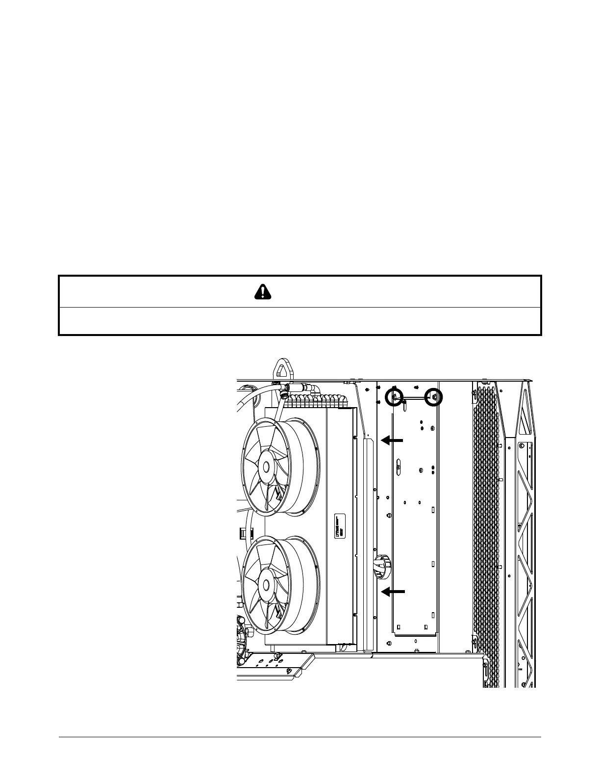
2. Use tape to attach protective material, such as cardboard, onto the rear of the heat-exchanger
assembly to protect the cooling fins.
3. Use a 10 mm,
hexagonal-socket wrench
to remove the 2 nuts on the
internal sheet metal.
4. Pull in the sheet metal to
access the inrush resistor.
CAUTION
Sharp cooling fins can cause cuts. Use caution when you work near the cooling fins.