Torch Connect Console
124 810410 Field Service Bulletin XPR170
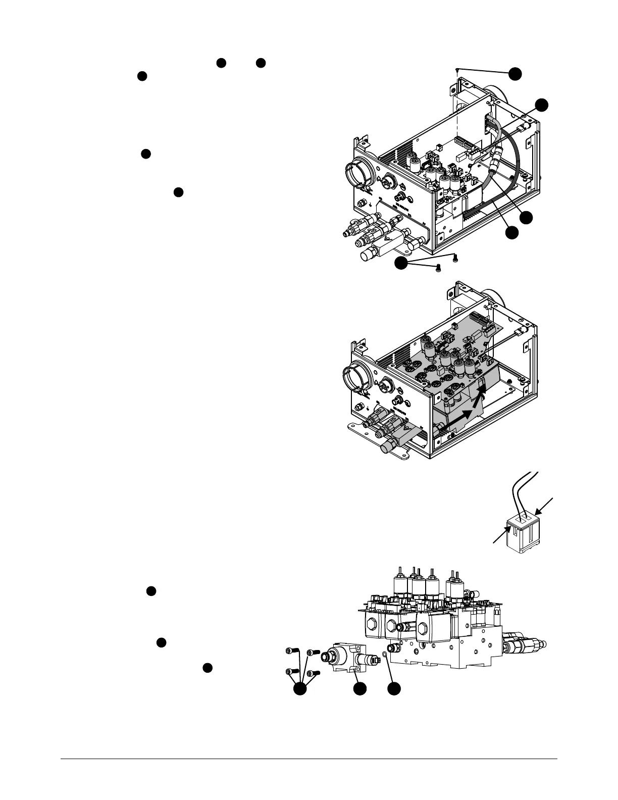
6. Disconnect the yellow , blue , and
black tubes from the push-to-connect
fittings on the manifold assembly. Refer to
How to use push-to-connect fittings on
page 102.
7. Use a Phillips screwdriver to remove the
screw from the control PCB.
8. Use a 3 mm, hexagonal-key wrench to remove
the 2 screws that hold the manifold
assembly in the bottom of the torch connect
console.
9. Slide the manifold assembly with control PCB
back and lift out.
10. Use the edge of the connector to disconnect
the wire for V11 from the control PCB.
Be careful not to pull the wires out of the solenoid valve connector.
11 . Use a 5 mm, hexagonal-key
wrench to remove the 4
screws from the bottom
manifold assembly.
12. Remove the bottom manifold
assembly .
13. Remove the O-ring from the
inlet manifold.