One DS5100 and DS5300 and four EXP5000 storage expansion
enclosures
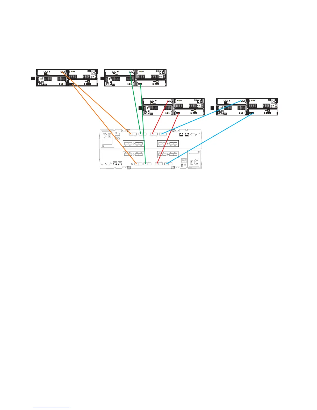
Figure 53 shows the cabling scheme for one DS5100 and DS5300 and four
EXP5000 storage expansion enclosures.
Perform the following steps to connect four EXP5000 storage expansion enclosures
to one DS5100 and DS5300:
1. Connect port 8 of drive channel 1 on the DS5100 and DS5300 to port 1B on the
left ESM of the first EXP5000 (1).
2. Connect port 1 of drive channel 5 on the DS5100 and DS5300 to port 1B on the
right ESM of the first EXP5000 (1)
3. Connect port 6 of drive channel 2 on the DS5100 and DS5300 to port 1B on the
left ESM of the second EXP5000 (2).
4. Connect port 3 of drive channel 6 on the DS5100 and DS5300 to port 1B on the
right ESM of the second EXP5000 (2).
5. Connect port 4 of drive channel 3 on the DS5100 and DS5300 to port 1B on the
left ESM of the third EXP5000 (3).
6. Connect port 5 of drive channel 7 on the DS5100 and DS5300 to port 1B on the
right ESM of the third EXP5000 (3).
7. Connect port 2 of drive channel 4 on the DS5100 and DS5300 to port 1B on the
left ESM of the fourth EXP5000 (4).
8. Connect port 7 of drive channel 8 on the DS5100 and DS5300 to port 1B on the
right ESM of the fourth EXP5000 (4).
One DS5100 and DS5300 and eight EXP5000 storage expansion
enclosures
Figure 54 on page 83 shows the cabling scheme for one DS5100 and DS5300 and
eight EXP5000 storage expansion enclosures.
3
36
63
EXP810/EXP5000
ds50084
36
63
EXP810/EXP5000
36
63
EXP810/EXP5000
2
4
1
36
63
EXP810/EXP5000
Figure 53. One DS5100 and DS5300 and four EXP5000 storage expansion enclosures
82 IBM System Storage DS5100 and DS5300 Storage Subsystem: Installation, User’s, and Maintenance Guide