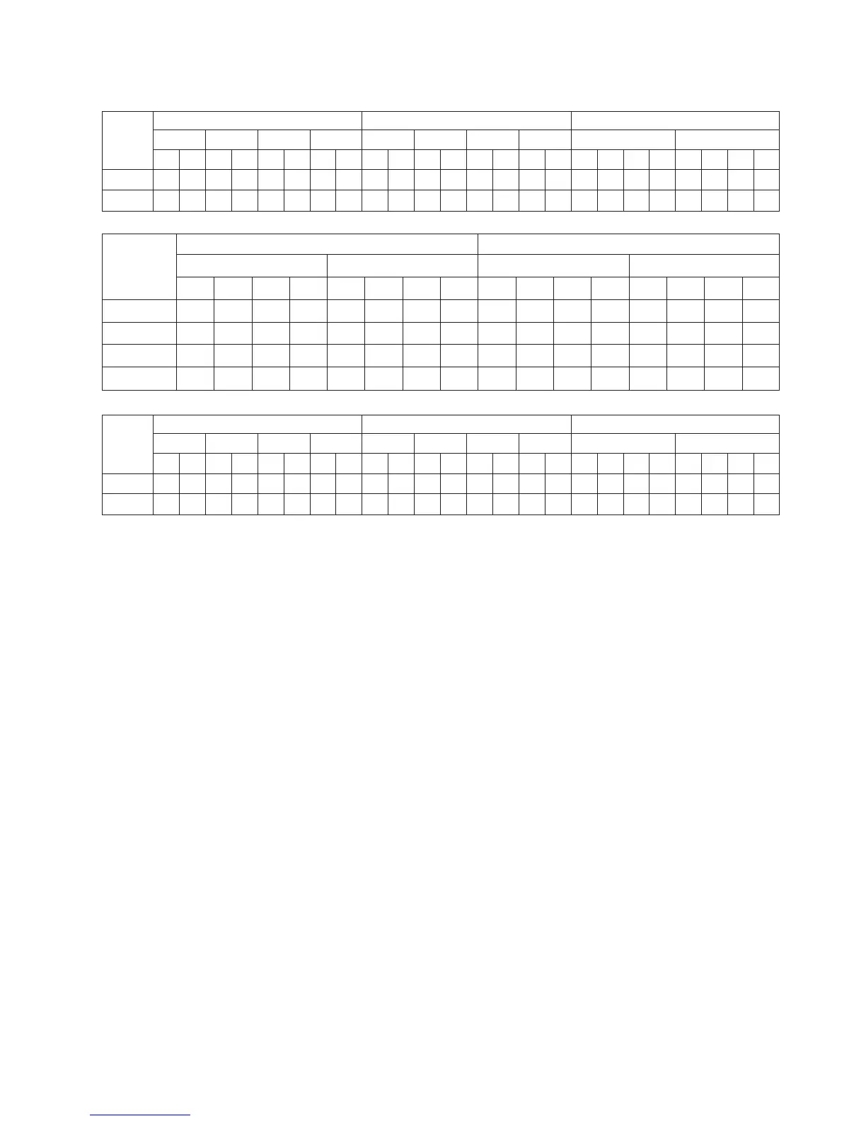
Table 42. Cabling for five to eight EXP5060s, storage expansion enclosures 7 and 8 with drive-side trunking
Cable
Controller A Controller B Storage Expansion Enclosure 7
Ch1 Ch2 Ch3 Ch4 Ch5 Ch6 Ch7 Ch8 ESM A (Top) ESM B (Bottom)
87654321123456781A1B2A2B1A1B2A2B
1X X
2X X
Cable
Storage Expansion Enclosure 7 Storage Expansion Enclosure 8
ESM A (Top) ESM B (Bottom) ESM A (Top) ESM B (Bottom)
1A 1B 2A 2B 1A 1B 2A 2B 1A 1B 2A 2B 1A 1B 2A 2B
3X X
4X X
5XX
6XX
Cable
Controller A Controller B Storage Expansion Enclosure 8
Ch1 Ch2 Ch3 Ch4 Ch5 Ch6 Ch7 Ch8 ESM A (Top) ESM B (Bottom)
87654321123456781A1B2A2B1A1B2A2B
7 XX
8 XX
Cabling the storage expansion enclosures to a storage subsystem
Complete the following steps to cable the storage expansion enclosures to a
DS5100 and DS5300:
1. Install an SFP module in the drive mini hub port on the back of the Storage
Subsystem, as shown in Figure 69 on page 106.
2. Connect an LC-LC fiber-optic cable into the SFP module, as shown in Figure 70
on page 106.
Chapter 3. Cabling the storage subsystem 105