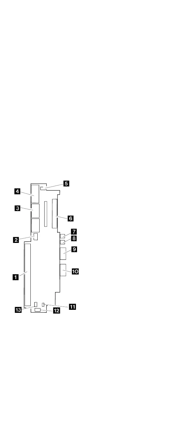
Main Board
.1/ AT Slot (98-pin)
.2/ Power Unit Connector
.3/ Internal SCSI Connector
.4/ Internal Hard Disk Drive Connector
.5/ Buzzer Connector
.6/ I/O Card Interface
.7/ Audio-Out Jack
.8/ Speaker-In Jack
.9/ External Display Connector
.1ð/ Video-In Connector
.11/ Security Feature Microswitch Interface (CN 22)
.12/ LED Cable Connecter
.13/ Key Lock Assy. Microswitch Interface (CN 21)
Note: Switch 1, switch 4, and all 4- and 8-position DIP
switches have no effect on system operation. The
settings for other switches can be found in the
User's Guide
.
382 IBM Mobile Systems HMM - Volume 1
 Loading...