EasyManuals Logo

IBM StorVize V7000 Gen2 User Manual

IBM StorVize V7000 Gen2
188 pages
To Next Page IconTo Next Page
To Previous Page IconTo Previous Page
Page #106 background imageLoading...
Page #106 background image
For more information about the power supply indicators, see “Storwize V7000
2076-92F expansion enclosure LEDs and indicators” on page 131.
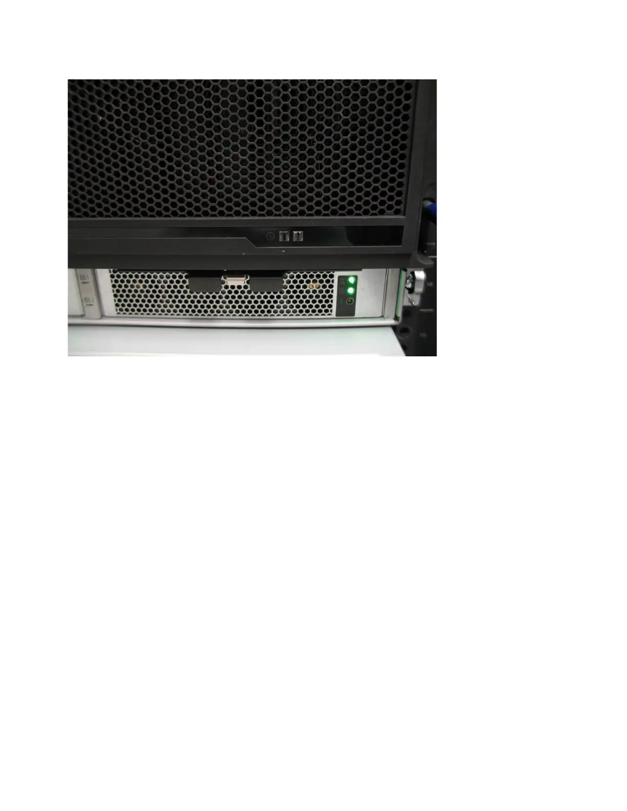
Removing the fascia: 2076-92F
To perform service tasks, you can remove each component of the fascia from the
front of a 2076-92F expansion enclosure.
About this task
The expansion enclosure has a 4U front fascia that covers the display panel and a
1U fascia that covers the power supply units (PSUs). As Figure 75 on page 83
shows, the fascias are independent; you can remove or replace one without having
to remove or replace the other.
svc01032
Figure 74. Power supply indicators
82 Storwize V7000 Gen2 and Gen2+: Quick Installation Guide

Table of Contents

Questions and Answers:

Question and Answer IconNeed help?

Do you have a question about the IBM StorVize V7000 Gen2 and is the answer not in the manual?

IBM StorVize V7000 Gen2 Specifications

General IconGeneral
CategoryStorage
Maximum Drives504
RAID Levels0, 1, 5, 6, 10
Operating SystemIBM Spectrum Virtualize
Power SupplyDual redundant power supplies
Input Voltage100-240 V AC
Humidity8% to 80% non-condensing
ModelStorwize V7000 Gen2
Drive InterfaceSAS
Form Factor2U
Drive Types SupportedSAS SSDs, SAS HDDs
Host Interface8 Gb FC, 16 Gb FC, 10 Gb iSCSI
Nodes2
Operating Temperature10°C to 35°C
Non-operating Temperature-10°C to 50°C

Related product manuals