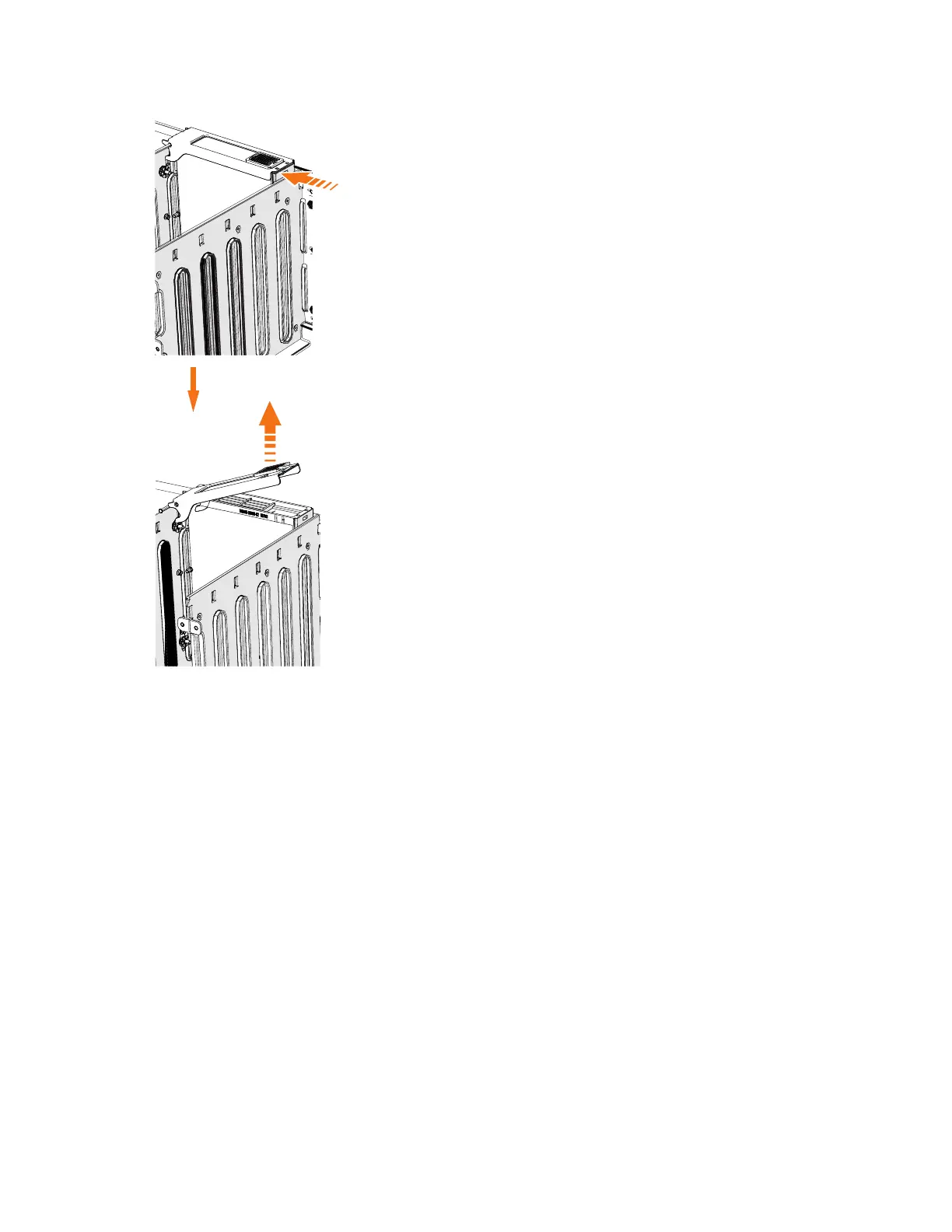
EasyManuals Logo

IBM StorVize V7000 Gen2 User Manual

IBM StorVize V7000 Gen2
188 pages
To Next Page IconTo Next Page
To Previous Page IconTo Previous Page
Page #129 background imageLoading...
Page #129 background image
6. Lift the handle (2) to unlock the drive carrier from the partition, as shown in
Figure 92. Ensure the toe on the bottom of the latch is fully disengaged.
7. Carefully lift the drive carrier up to remove it from the expansion enclosure.
8. Repeat step 4 on page 103 through step 7 for each drive you need to remove.
Replace the drive
9. To reinstall a drive, or replace it with one from FRU stock, follow the procedure
in “Installing or replacing a drive: 2076-92F” on page 69.
Removing a secondary expander module: 2076-92F
You can remove a secondary expander module from a 2076-92F expansion
enclosure if it is faulty or to perform other service tasks.
1
2
svc00983
Figure 92. Remove the drive assembly
Chapter 2. Installing the Storwize V7000 Gen2 and Storwize V7000 Gen2+ hardware 105

Table of Contents

Questions and Answers:

Question and Answer IconNeed help?

Do you have a question about the IBM StorVize V7000 Gen2 and is the answer not in the manual?

IBM StorVize V7000 Gen2 Specifications

General IconGeneral
CategoryStorage
Maximum Drives504
RAID Levels0, 1, 5, 6, 10
Operating SystemIBM Spectrum Virtualize
Power SupplyDual redundant power supplies
Input Voltage100-240 V AC
Humidity8% to 80% non-condensing
ModelStorwize V7000 Gen2
Drive InterfaceSAS
Form Factor2U
Drive Types SupportedSAS SSDs, SAS HDDs
Host Interface8 Gb FC, 16 Gb FC, 10 Gb iSCSI
Nodes2
Operating Temperature10°C to 35°C
Non-operating Temperature-10°C to 50°C

Related product manuals